I'm thinking about going to 211 monos in SET, but I don't know of any good schematics to start with...something preferably tube rectified would be nice, not too sure if DC heaters are used on 211's but I've had good luck with them on the SV811's...
Can anyone point me in the right direction?
Thanks 🙂
Can anyone point me in the right direction?
Thanks 🙂
Bump for the zombie thread!
Same question really. A friend is passing a non-working but otherwise complete 211 amp to me. The amp was working, but died. It seems a fantastic opportunity to build a new circuit using the existing valves & iron.
So can someone point me towards a really good circuit?
Tia,
Fran
Same question really. A friend is passing a non-working but otherwise complete 211 amp to me. The amp was working, but died. It seems a fantastic opportunity to build a new circuit using the existing valves & iron.
So can someone point me towards a really good circuit?
Tia,
Fran
Can't speak to how good it is but, I recall recently looking this one over.
Electra-Print.com 211 A2 Amplifer
Electra-Print.com 211 A2 Amplifer
I am going to do something similar to what George Tubelab did:
http://www.diyaudio.com/forums/tube...how-go-building-monster-se-3.html#post2639855
http://www.diyaudio.com/forums/tube...how-go-building-monster-se-3.html#post2639855
Thanks guys, good food for thought there. Apparently the amp sounded great but was a bit unreliable. I'm supposed to get it this weekend so I'll draw up the schematic and post it here.
Any other suggestions - I would only need around 5w or so, so I don't need to wring 30 or 40 watts out the amp....
Fran
Any other suggestions - I would only need around 5w or so, so I don't need to wring 30 or 40 watts out the amp....
Fran
The question kinda comes off like can you suggest any cars I can buy/build with a V8 engine?
😛
More info about the chassis, iron, supply voltages and current, and output iron sets a few limits - that and what type of application and performance you want...
The drive circuit is very important with a 211... so start by thinking about what you will use in that hole?
_-_-bear
😛
More info about the chassis, iron, supply voltages and current, and output iron sets a few limits - that and what type of application and performance you want...
The drive circuit is very important with a 211... so start by thinking about what you will use in that hole?
_-_-bear
The question kinda comes off like can you suggest any cars I can buy/build with a V8 engine?
😛
More info about the chassis, iron, supply voltages and current, and output iron sets a few limits - that and what type of application and performance you want...
The drive circuit is very important with a 211... so start by thinking about what you will use in that hole?
_-_-bear
Thanks Bear - you are of course correct - when I get my hands on the amp this weekend I will have more info. I didn't know about the importance of the driver circuit either - good to know.
Fran
Hello
Here is one if you like it.
Goliath 211 single ended versterker (deel 3)
I'm in process to collect the parts for a GM70. I know at the beginning how confused I was which way to go....
At first you have decided about the parts U want to use, also 2 stage, 3 stage, inter stage transformer or with out etc.
After start to collect the parts. That way you can avoid to spend money on parts later they hold dust on the shelf etc.
The parts for these toys are not cheap!
Greetings gabor
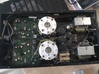
Well, I picked up the amp today. Substantial piece of kit alright. The amp is not working, some of the heaters aren't working, and there is a good bit of burning around the restifiers used for the heaters.It looks like the bridges are undersized or underheatsinked for what they were asked to do - you can see them in one of the pics below with the heatsink removed. The driver circuit is on a PCB and all the passives there look OK (except those heater rectifiers).
The driver circuit uses 2 x 12ax7, 3 x 12at7 and a 5681 I think. Those 211 valves are frickin' huge!!! All the main bits of hardware appear OK, so at least it won't (hopefully) cost much to fix. I also got a spare pair of 211s as well.
I took a few pics, but haven't even started to trace a circuit yet......
Fran
Attachments
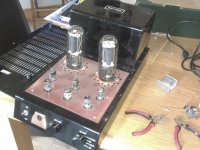
I meant to say earlier that the amp is a Gamma Acoustics Rhythm amp. Theres so little out there about these amps - 1 or 2 mentions and thats it!
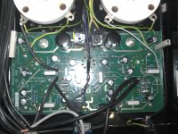
Anyway I did some more looking tonight and sorted some issues and found more. First off, the bridges for the heaters were cooked. There was 1 bridge for each 211 and then 1 for all the 12''7 valves. The 5687 runs off AC heaters. So I replaced all those and at least now all the heaters were working. So then I decided to check the B+. I get 1050V at the plates of the 211s (which seems correct). But I had only a couple of volts going to the PCB you see in the pic above which holds all the input and drivers. So anyway long story short, the 1050V B+ is filtered down using a massive 50K 50W resistor and it had gone open circuit. You can see a the big resistor in the middle pic above (theres 2 similar sized ones together in the pic).
What the hell could cause a 50W resistor like that to go open??!? Its a worry!!!
Also, I've carefully (visually) checked all the components on the PCB and other than the rectifiers, there's no sign at all of anything overheated.
So I'm guessing that the input/driver circuits are looking for about 300V or so. That would mean that if a 50K resistor provided a drop of ~700V, the resistor is throwing off ~11W or so.
Any comments? To quote pink floyd "is there anybody out there?" 🙂
Fran
No, 300V B+ is not enough to deliver 400V P-P. However, if you want to get something like 8W from this monsters, it may be Ok...
Resistor may be open because of shorted electrolytic capacitor?
Resistor may be open because of shorted electrolytic capacitor?
Last edited:
I don't know the order of failure, but with heaters of the 211 off B+ could have been well above 1050V, so the power dissipation of the dropping resistor inadequate. When you replace it resize it to cover a short, three 150K 20 watters ought to do. Before you build something “better” try to get that amp working and see what you think. Sounds like you are close.
Matt
Matt
If you take 1% of THD as the usable limit the 211 will not pull out more watts than a 300B. No much difference there & the 300B sounds better IMO and there are better parts due to the lower B+. Just a thought before starting all the trouble/fun with the 211 or 845.
I meant to say earlier that the amp is a Gamma Acoustics Rhythm amp. Theres so little out there about these amps - 1 or 2 mentions and thats it!
I remember a tube amp looking similar
maybe it was sold by Vacuum Tube Valley
not sure
Thanks guys!
I don't know what the original design point was for this amp, but seems similar to the airtight one that also uses 12ax7 and 211. I think there's a phonostage in this amp - that's probably why the extra valves are in there. Anyway next up is to get one of those resistors and try it out. It just seems strange that someone would design and build a monster amp like this but use such undersized rectifiers.
Anyway, let's see how it works out. It hasn't cost me anything so very little to lose!
Fran
Mmmm. That 50k resistor had a 500v rating. I wonder if this is part of why it died.
Fran
why do you say 500V
shouldn't you think wattage
500V ? that would mean almost no ampere, I guess
why do you say 500V
shouldn't you think wattage
500V ? that would mean almost no ampere, I guess
No, he is right. For example, wirewound resistor has spaces between wires that can be broken by certain voltage between them. Like a spark gap in a spark plug in the motor of your vehicle.
I have a Gamma Acoustics 300B amp( I think it is called "space" but it is buried at the bottom of a cupboard) stored at my home belonging to a friend of mine. It was giving trouble so I had a look at it for him. Build is rather weird; all small component are covered in heatshrink and are simply strapped between rather crude rails and the valve sockets themselves; totally different from the pictures posted.I get the impression that Gamma acoustic,whoever they are, tried a different construction technique every time they built something. It ate 300B's at a fantastic rate. It has a very smart case and this plus the ironmongery are the only thing I would bother keeping. If and when I have time, I will completely rebuild it; 2 new 300B's every few months is too expensive. The valve lineup is 5U4G, 6AS7, 6 X 6SN7 and a pair of 300B's. Output xformers are also peculiar and look as if they have been made from some sort of kit.
Well I found a few 5w 150k resistors in the parts box and stuck them in for a quick check. I now get a b+ of 400v for the drivers which would seem about right. Those dropping resistors are cooking though. They're not good enough for long term but it has allowed me to have a quick listen - sounds good alright (workshop system, but it's clean and deep).
I ordered parts today so should have better information when I get those in.
On the build quality: physically it looks good enough, but those rectifiers are the weak point. Also, there must be a more elegant way of producing 400v from 1100v. Dealing with heat is what has affected this amp I think. No wonder it was unreliable.
Fran
- Status
- Not open for further replies.
- Home
- Amplifiers
- Tubes / Valves
- Thinking about having a 211 SET amp built, anyone know of good schematics?