Where do you mount the thermistors (both at transformer and at GND)?
Mount them close to heatsink/body of amp or near the transformer?
Any pics of it?
Mount them close to heatsink/body of amp or near the transformer?
Any pics of it?
The power supply thermistors are not used for temperature sensing but for inrush current suppression. They limit surge current when powering up the amplifier by functioning as a power resistor which drops from a high cold resistance to a low hot resistance when heated by the current flowing through them. They do not need to be close to a source of heat.
Inrush current
If I am using a soft start circuit, I guess I will not need the Inrush Current Limiter?
Am I right on this one???
If I am using a soft start circuit, I guess I will not need the Inrush Current Limiter?
Am I right on this one???
I used this schematic, I wish I could give credit to whom it belongs. (I think it was Papa's from the F3 power supply) I just copied it. You are correct, if you have a different soft start circuit, you do not need the Themistors (in the startup circuitry).
Ron
Ron
Attachments
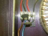
This is how i have done it. However I am a rookie at this so I would like to see other comments from experienced builders.
jim
Thanks for that picture, Max, I think I am going to copy your design... 🙂
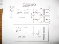
Additional question wrt thermistor and 240v transformer.
The PSU pic in the F5 doc that refers to 240v shows a dual 120v primary
(top part of pic)
If I only have a single 240v primary, is my alternate position correct (bottom part of pic) or am I going for a Darwin award?
tia for any life saving comments anyone would like to offer, else I guess I'll find out when I power the PSU part up tomorrow ;-)
cheers
Nick
The PSU pic in the F5 doc that refers to 240v shows a dual 120v primary
(top part of pic)
An externally hosted image should be here but it was not working when we last tested it.
If I only have a single 240v primary, is my alternate position correct (bottom part of pic) or am I going for a Darwin award?
tia for any life saving comments anyone would like to offer, else I guess I'll find out when I power the PSU part up tomorrow ;-)
cheers
Nick
This is how i have done it in my F2 clone. However i am concerned that 10 Ohms series resistance does not reduce the inrush current enough. With a 240v supply and 10 Ohms series resistance (ignoring the resistance of the primary winding for now) the inrush current is 24 Amps. i am using a 625VA toroid and when i checked the resistance across the primary winding including the series CL60 thermistor it measured 14 Ohms. Is there a better way to measure the series resistance of the primary winding?
I'd like to hear some experienced voices on this issue... is a single CL60 enough with a 240V supply?
Cheers,
mymindinside
I'd like to hear some experienced voices on this issue... is a single CL60 enough with a 240V supply?
Cheers,
mymindinside
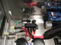
link's broken, hopefully this works
An externally hosted image should be here but it was not working when we last tested it.
in both cases - xformer feels extremely bored - it just don't care where NTC is located .... as long it is in line with mains

Don't worry about the transformers being lonely - won't be long before they get to earn their keep 😀
Thanks for the confirmation (and encouragement)
cheers
Nick
Thanks for the confirmation (and encouragement)
cheers
Nick
Thanks.
Checked it all out today and it fired up fine, series light bulb glowed briefly and then went out. 25.4v each side, nice and steady.
On to the next stage now 😀
cheers
Nick
Checked it all out today and it fired up fine, series light bulb glowed briefly and then went out. 25.4v each side, nice and steady.
On to the next stage now 😀
cheers
Nick
Sorry, my lack of clarity - there's no load attached :-( and the lightbulb is in series with the mains live (no variac so I wired up a The Dim-bulb Radio Tester).
Leaving it running for a while and I get a steady 25.4v ish each side of the supply (which I work out as right for 18v secondary * 1.414, and allowing for mains to wander about a bit)
I'm waiting for my thermal paste before I can attach the F5's and start biasing up
cheers
Nick
Leaving it running for a while and I get a steady 25.4v ish each side of the supply (which I work out as right for 18v secondary * 1.414, and allowing for mains to wander about a bit)
I'm waiting for my thermal paste before I can attach the F5's and start biasing up
cheers
Nick
Has anyone happen to find this wired thermistor used in the J2 for sale anywhere? Looks perfect for my application:
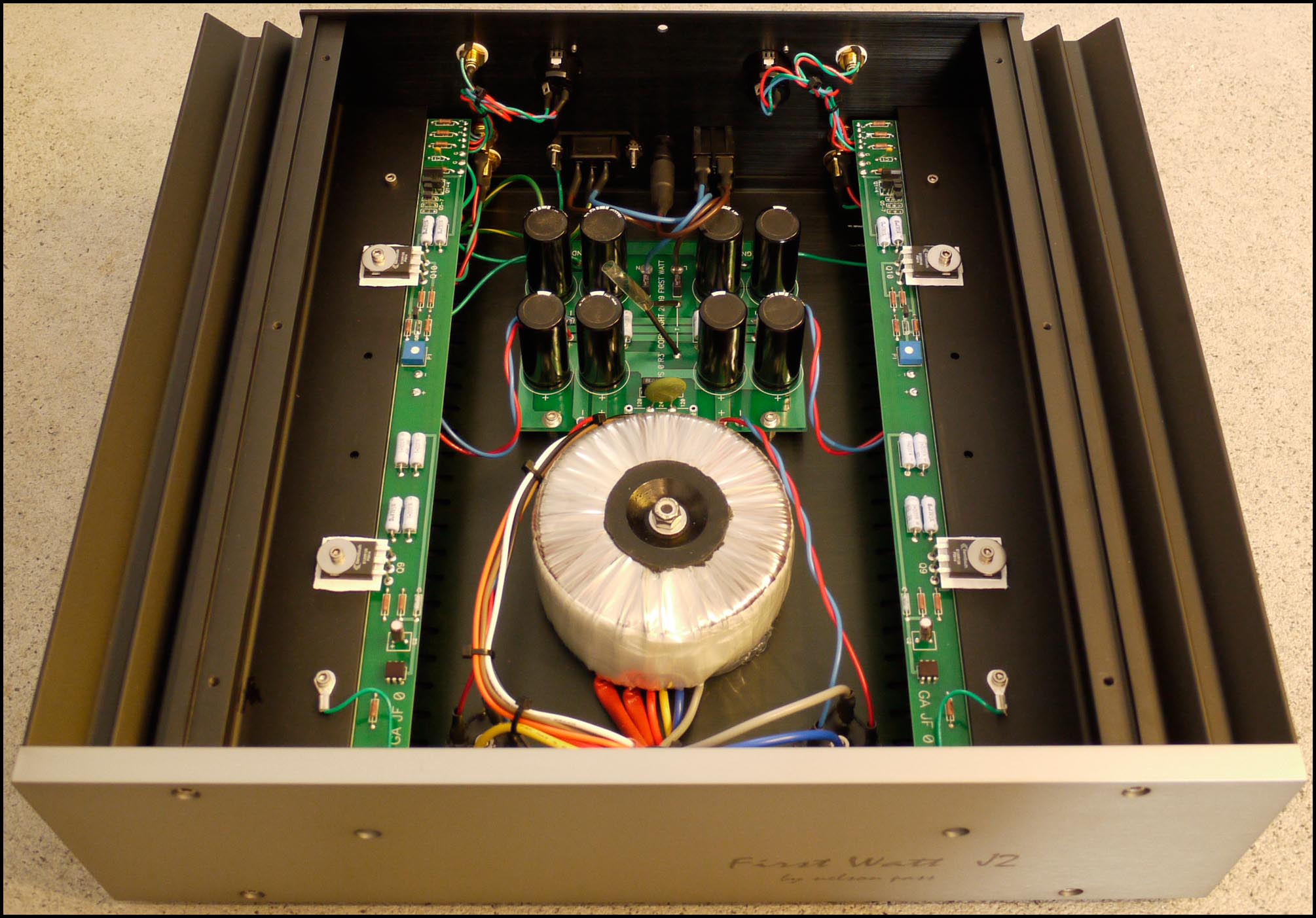
Nothing that is available at Mouser or Digikey with CL60 in the title, plus searches for leaded thingys. I'm not sure if Papa insulated the leads and added that plastic cover thing, I was assuming not.
- Status
- Not open for further replies.
- Home
- Amplifiers
- Pass Labs
- Thermistor Location for F5 power supply