Hi,
I am fixing my Orion and need to replace the thermal pad under and above the BJT.
I have thought about using mica and thermal paste, but mica sheets are not easy to find.
What do you use? (economical but safe choice).
Is Kapton okay?
From Italy I generally buy from Rs-component, Mouser, Farnell ..
Thanks for your attention. 🙂
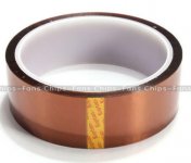
Yes. It's generally 1 mil thick with 1.5-2 mils of adhesive.
Yes, you must use heatsink compound between the semiconductors and the tape.
What are you using to replace the double-sided tape on the clamps?
Yes, you must use heatsink compound between the semiconductors and the tape.
What are you using to replace the double-sided tape on the clamps?
Yes, I understood.
I was thinking of fixing a kaptan strip on the bars as well, put the thermal paste there too and tighten the bar with screws.
So kaptan between the chassis and the BJTs and Kaptan between the bar and the BJTs.
Thank you
I was thinking of fixing a kaptan strip on the bars as well, put the thermal paste there too and tighten the bar with screws.
So kaptan between the chassis and the BJTs and Kaptan between the bar and the BJTs.
Thank you
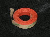
The double-sided tape on the bars is to distribute the clamping force evenly.
If you use double-sided tape like the original, you must re-tighten the screws several times as the amp heats up during bench-testing.
Using a high-temperature silicone rubber (below) doesn't require re-tightening.
If you use double-sided tape like the original, you must re-tighten the screws several times as the amp heats up during bench-testing.
Using a high-temperature silicone rubber (below) doesn't require re-tightening.
Attachments
Thinking about it, you are absolutely right !! 😉
I wanted to thank you, both for the answers and for the many threads you wrote. I have read a lot of them and they have been of great help to me in repairing my 2150GX.
I write two lines (may be more 😀) to illustrate the situation.
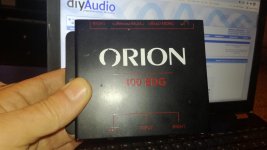
My brother gave me one of his 2 Orion 2150gx as a gift.
I bridged it with the BDG400 module and after 20 seconds of operation it broke.
- Power fuse burned out
- Left Channel burned out: the MSPU57 driver, a 2n6488 and a 6491.
Consider that it works smoothly ... my sub can withstand max 200w rms, compared to the 600w rms that the orion should push to BDG@4ohm.
I replaced the components with original, Motorola MSPU, but the 2n64xx with ON. Motorola can't find any more.
I tested everything on the bench, resistors values, diode, power supply voltages, (about +/- 39V and +/- 13.9V). So on the bench I tried to make it play low power in stereo, no problem, sounds good.
I put it back in the car (bridge configuration) and after 20 seconds it burned out again.
-Blown fuse
-Left channel burnt.
Also in this case some final on the NPN and PNP side, but this time both the NPN and the PNP drivers, the MPSU07 and 57.
Also one of the 27 ohm resistors on the base of the BJT.
I repaired it again, checked and tested everything and finally decided to swap the amps I have in the car, using the 2150gx in a 4 ohm stereo configuration, eliminating the BDG400.
(There is a bit of confusion ... there are those who say that 2150 can bridge, there are those who say no. I think I can .... but I didn't want to break it again. I love old school, but I'm starting to spend too much on replacement parts).
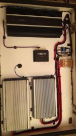
It worked great for 2/3 hours. Then while I was trying to calibrate the system (TA, cross-over, level, EQ, etc.) it suddenly turned off .... with relative smoke in the car, pushed by the fans ...
I immediately put my hands on all the amps, to understand IF they were burning, but nothing ... even he wasn't even lukewarm.
This time the fuse was good.
I opened the amplifier and the damage this time much more extensive. 😡
- 8+8 power supply BJT all broken.
- As USUAL left channel: one NPN and one PNP and one driver (i have to check the others..)
It seems clear to me that there is a problem on the left channel, maybe some tantalum capacitor that under stress, could trigger some inaudible high frequency noise, with the consequences I have seen ..
So I think I just reconnect a couple of transistors for the power supply, and maybe try to compare on the bench, left and right channel from input to output, sending a small sine wave. Maybe I find some discrepancies. 🙄
Unfortunately, if the problem only occurs under stress, it will be difficult to simulate it on the bench, I don't have such a powerful power supply.
Perhaps the best solution is to first replace all the caps (tantalum, electrolytic) and then perform some measurements to see if the pre-amp part is identical on the two channels.
I suspect that the cause of all these breakdowns is not the BJTs or the drivers, but something that overloads them.
Any suggestion is welcome!! 🙂
I wanted to thank you, both for the answers and for the many threads you wrote. I have read a lot of them and they have been of great help to me in repairing my 2150GX.
I write two lines (may be more 😀) to illustrate the situation.
My brother gave me one of his 2 Orion 2150gx as a gift.
I bridged it with the BDG400 module and after 20 seconds of operation it broke.
- Power fuse burned out
- Left Channel burned out: the MSPU57 driver, a 2n6488 and a 6491.
Consider that it works smoothly ... my sub can withstand max 200w rms, compared to the 600w rms that the orion should push to BDG@4ohm.
I replaced the components with original, Motorola MSPU, but the 2n64xx with ON. Motorola can't find any more.
I tested everything on the bench, resistors values, diode, power supply voltages, (about +/- 39V and +/- 13.9V). So on the bench I tried to make it play low power in stereo, no problem, sounds good.
I put it back in the car (bridge configuration) and after 20 seconds it burned out again.
-Blown fuse
-Left channel burnt.
Also in this case some final on the NPN and PNP side, but this time both the NPN and the PNP drivers, the MPSU07 and 57.
Also one of the 27 ohm resistors on the base of the BJT.
I repaired it again, checked and tested everything and finally decided to swap the amps I have in the car, using the 2150gx in a 4 ohm stereo configuration, eliminating the BDG400.
(There is a bit of confusion ... there are those who say that 2150 can bridge, there are those who say no. I think I can .... but I didn't want to break it again. I love old school, but I'm starting to spend too much on replacement parts).
It worked great for 2/3 hours. Then while I was trying to calibrate the system (TA, cross-over, level, EQ, etc.) it suddenly turned off .... with relative smoke in the car, pushed by the fans ...
I immediately put my hands on all the amps, to understand IF they were burning, but nothing ... even he wasn't even lukewarm.
This time the fuse was good.
I opened the amplifier and the damage this time much more extensive. 😡
- 8+8 power supply BJT all broken.
- As USUAL left channel: one NPN and one PNP and one driver (i have to check the others..)
It seems clear to me that there is a problem on the left channel, maybe some tantalum capacitor that under stress, could trigger some inaudible high frequency noise, with the consequences I have seen ..
So I think I just reconnect a couple of transistors for the power supply, and maybe try to compare on the bench, left and right channel from input to output, sending a small sine wave. Maybe I find some discrepancies. 🙄
Unfortunately, if the problem only occurs under stress, it will be difficult to simulate it on the bench, I don't have such a powerful power supply.
Perhaps the best solution is to first replace all the caps (tantalum, electrolytic) and then perform some measurements to see if the pre-amp part is identical on the two channels.
I suspect that the cause of all these breakdowns is not the BJTs or the drivers, but something that overloads them.
Any suggestion is welcome!! 🙂
Do you have an oscilloscope?
When you have groups of parallel transistors and one in the group fails, you must replace all in that group with (relatively well) matched transistors. Generally, having all in the group from the same production batch (same date code), is good enough.
When you have groups of parallel transistors and one in the group fails, you must replace all in that group with (relatively well) matched transistors. Generally, having all in the group from the same production batch (same date code), is good enough.
Yes I have three oscilloscope... but at my parents' house.
Recently my dad bought a digital one, better than the old cathode ray tube ones. I have to go get it ...
Meanwhile I was preparing the list of broken components to order them.
I know that the best would be to use "selected in pairs" transistors, but finding them is impossible and would be very expensive.
However, I must say in your favor that in both breaks, the same transistors that I had previously changed burned out.
As I told you, they are not Motorola, they are ON, but reading a bit of history, when Motorola stopped producing them, they passed the patent to ON.
Reading the two datasheets they are identical! 🙄
Anyway, since I have to change 16 for the power supply, it costs me little to change also, all the final stage of the Left channel. I will follow your advice.
Having said that, I always remain of the idea that the cause of the breakages is elsewhere...especially because the driver burns out ....😕
Recently my dad bought a digital one, better than the old cathode ray tube ones. I have to go get it ...
Meanwhile I was preparing the list of broken components to order them.
Sound strange. If a Transistor works (checked) why replace it?When you have groups of parallel transistors and one in the group fails, you must replace all in that group with (relatively well) matched transistors.
I know that the best would be to use "selected in pairs" transistors, but finding them is impossible and would be very expensive.
However, I must say in your favor that in both breaks, the same transistors that I had previously changed burned out.
As I told you, they are not Motorola, they are ON, but reading a bit of history, when Motorola stopped producing them, they passed the patent to ON.
Reading the two datasheets they are identical! 🙄
Anyway, since I have to change 16 for the power supply, it costs me little to change also, all the final stage of the Left channel. I will follow your advice.
Having said that, I always remain of the idea that the cause of the breakages is elsewhere...especially because the driver burns out ....😕
How do you define 'better' when judging the quality of a scope?
Even though transistors with the same part number have the same specifications, they are not identical. The best chance to get a reliable amp is to use matched (date code) parts. You don't need to have them matched precisely like you find with some of the differential pairs.
When transistors are in parallel, they should all carry the load equally. Transistors that aren't closely matched will perform differently. Depending on various things like temperature, current flow... some in a parallel group may be taking all of the load.
The same thing, regarding matching, applies to the emitter resistors. If one fails in a group, all should be replaced with resistors from the same batch. They are not generally marked with production codes but if you buy a box of them or in an ammo pack, you know that they're likely very close.
Are you buying parts from reputable distributors?
The MPS-Ux7 transistors have been obsolete for years. Are you sure that you're not getting counterfeit parts?
You mentioned bridging earlier. Maybe the confusion was whether the amp could be bridged without the module.
Perry Babin;6592681]How do you define 'better' when judging the quality of a scope?
Very easy! knobs, many buttons and many colored lights !!
I'm kidding of course. 😀
I can guarantee you that I have great equipments, I don't remember the models, but I will send you the photos this week ... just to make me cool. 😀
Even though transistors with the same part number have the same specifications, they are not identical. The best chance to get a reliable amp is to use matched (date code) parts. You don't need to have them matched precisely like you find with some of the differential pairs.
When transistors are in parallel, they should all carry the load equally. Transistors that aren't closely matched will perform differently. Depending on various things like temperature, current flow... some in a parallel group may be taking all of the load.
The same thing, regarding matching, applies to the emitter resistors. If one fails in a group, all should be replaced with resistors from the same batch. They are not generally marked with production codes but if you buy a box of them or in an ammo pack, you know that they're likely very close.
It is clear, but even in the same production batch, especially for the transistors, it is not certain that they are all very similar. To do a good job you should select them, measure Hfe and choose them ...
Then buy 50 (25 npn and 25 pnp) and select 4 + 4 ....
I love sound quality, but I don't have to go to Mars.
However, as I told you, at this point I will also change the entire final stage, taking them from the same supplier.
About MPSUxx, I honestly don't know. It is an Italian seller, the logo is the Motorola one ... but you know, the Chinese are everywhere ...Are you buying parts from reputable distributors?
The MPS-Ux7 transistors have been obsolete for years. Are you sure that you're not getting counterfeit parts?
I will probably take the components to be replaced from Mouser, they also have the Cen-u07 and 57, do you think it is appropriate to buy them and replace the ones I have already changed? (I still have a couple of "motorola 😕" new ones)
You mentioned bridging earlier. Maybe the confusion was whether the amp could be bridged without the module.
No confusion ..I know, it's rare, but I have the bdg400 ...
And it's not like it's Pandora's box anyway.
I could easily build it with a 1: 1 gain inverting Op-Amp and a handful of components, leaving out the other functions it does (mixed mono, summed mono, left channel, right channel etc.)
As I told you before, in the last test in the car, I had removed the bdg400 and used the Orion in Stereo configuration configuration (load 4 ohm).
Attachments
I've never seen an LCD scope that I'd choose over my CRT scopes.
The confusion appeared to by by those who were arguing about bridging the 2150.
The CEN transistors are more likely to be reliable.
Doesn't your statement of "Sound strange. If a Transistor works (checked) why replace it?" contradict what you wrote here?
Yes. It's easy to build a bridging module (channel inverter).
Index of /temp/dinbridgingmodule
I've never seen an LCD scope that I'd choose over my CRT scopes.
me too, always used crt (a pair of Tektronix, one of which was a top model at the time) even though I haven't used it for a while (commitments, family, short time).
However, since dad got a new device (light, small, more practical and certainly more modern) why not use it or learn how to do it?
Only a few euros, it is better for me to change them rather than risk blowing up the BJT again. Tnks 😉The CEN transistors are more likely to be reliable.
I don't understand what's strange ..Doesn't your statement of "Sound strange. If a Transistor works (checked) why replace it?" contradict what you wrote here?
Yes. It's easy to build a bridging module (channel inverter).
I just thought that since I couldn't have selected BJTs, I might as well leave the working ones and replace the broken ones.
What does a simple inverting Op have to do with it?
It wouldn't be the first time I've used them ...
Maybe I misunderstood, or I don't express myself correctly, as I said in my recent presentation, English is not my language. I try to do my best.
I just finished checking; regarding the drivers, this time only one MPSU57 broke.
I'll be busy tomorrow, but I'll keep you updated on developments ...
Thanks for your attention. 😉
I have an LCD based scope but only use it when I need to capture some sort of glitch. The display on a good CRT based scope is far superior to most all of the LCD based scopes. For me, the information provided by a digital scope is mostly useless to me. It's a personal preference.
You mentioned building a module so I posted a simple one.
You mentioned building a module so I posted a simple one.
that's why I didn't understand ... I missed the link !!! 🙂
Thanks.
if I am not mistaken, I had already seen it on this forum .... as I told you I have read many of your posts ... and not just yours.
I've used the LCD one time, for 10 minutes... just to find the clipping level of my HU...
So I can't express a judgment in this sense ... maybe soon I will be able to tell you more.
- Home
- General Interest
- Car Audio
- Thermal pad or Kapton for Orion 2150gx?