I finally got hold of a scope to measure the the noise of the power supply I built, and I am a bit surprised.
The schematic I built is the following:
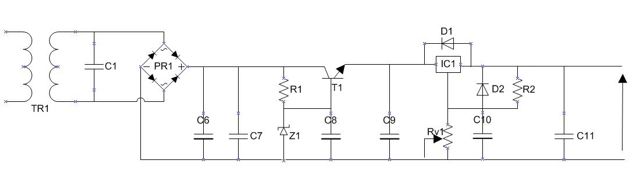
It is a two stage supply ending up with a LM317. Contrary to the schematic I am using a 12v car battery as the supply (so I forgo the transformer and the rectifier) and I output 3.35v.
The draw is probably between 0.8 to 1.2Amps.
From the LM327 spec I though I would get 70db noise rejection.
Yet measured with the scope, when the device connected to it is idle I can see a small ripple with a peak at 80mV and with a full load I get a ripple of 300mV peak to peak.
To calculate the noise rejection I do 20Log(0.3/3.35) and get 20db which is much lower than the theoretical 70db!
Did I make a mistake? What can explain such a difference or how can I improve this figure?
The schematic I built is the following:
It is a two stage supply ending up with a LM317. Contrary to the schematic I am using a 12v car battery as the supply (so I forgo the transformer and the rectifier) and I output 3.35v.
The draw is probably between 0.8 to 1.2Amps.
From the LM327 spec I though I would get 70db noise rejection.
Yet measured with the scope, when the device connected to it is idle I can see a small ripple with a peak at 80mV and with a full load I get a ripple of 300mV peak to peak.
To calculate the noise rejection I do 20Log(0.3/3.35) and get 20db which is much lower than the theoretical 70db!
Did I make a mistake? What can explain such a difference or how can I improve this figure?
Need component values!
Also, what frequency is the ripple, twice line frequency or ultrasonic?
Does the waveform at the emitter of T1 look sane?
Regards, Dan.
Also, what frequency is the ripple, twice line frequency or ultrasonic?
Does the waveform at the emitter of T1 look sane?
Regards, Dan.
A few things come to mind...
1. You have to pay as much attentention to PSU layouts as you do amplifier circuits. It's vital you use a "correct" ground to use for the 'scope.
2. Grounding again... and beware safety... but is the 'scope mains grounded as well as the PSU (via whatever it supplies).
3. Try clipping the probe tip and ground together (shorting the 'scope input) which should give a fine trace. Keeping them shorted connect to the ground in the psu. Does any ripple or noise "appear".
4. Is the load current drawn from the PSU steady (such as a resistor or linear amp) or is it feeding a circuit that runs at HF drawing, such as a Class D amp.
5. Remember any specs for the reg apply only when measured at the correct points (layout and grounding again) so that means measuring on the output pin of the reg and it's feedback ground point.
Last edited:
Barring connection problems, to get that much under-load ripple, C9 and/or C11 must be too small in value. For the output voltage & current, I would suggest at least 3300uf on C9 and 5600uf min on C11. The bigger the better on both. Your main input filter cap should also be large, even with battery(or especially with battery, for lower supply impedance).
Thank you for the feedback. I am going to try to answer your questions.
The component values:
C6 10000uF 25v
C7 0.1uF 63v film cap
Z1 Zener 8v2 1.3W
R1 75 Ohm 1/2 Watt
T1 TIP31C
C8 10uF 25v Tantal
C9 1uF 25v Tantal
Rv1 Variable 1KOhm 1/4 Watt
IC1 LM317T
D1 & D2 1N4001
R2 240 Ohm 1/4 Watt
C10 47uF 25v Tantal
C11 1uF 63v + Nichicon 10uF 35v in parallel
I looking at C9 with the scope (right after T1, yes I get the same waveform and about 300mv "ripple" for 8.2v output.
Could it be that using 2 stages is a bad thing and it would be better with just the regulator?
The load is activc an Apple Airport express (wifi, processor, dac)
Here are the wave forms:
- idle
- with full load
The circuit from the top:
The component values:
C6 10000uF 25v
C7 0.1uF 63v film cap
Z1 Zener 8v2 1.3W
R1 75 Ohm 1/2 Watt
T1 TIP31C
C8 10uF 25v Tantal
C9 1uF 25v Tantal
Rv1 Variable 1KOhm 1/4 Watt
IC1 LM317T
D1 & D2 1N4001
R2 240 Ohm 1/4 Watt
C10 47uF 25v Tantal
C11 1uF 63v + Nichicon 10uF 35v in parallel
I looking at C9 with the scope (right after T1, yes I get the same waveform and about 300mv "ripple" for 8.2v output.
Could it be that using 2 stages is a bad thing and it would be better with just the regulator?
The load is activc an Apple Airport express (wifi, processor, dac)
Here are the wave forms:
- idle
An externally hosted image should be here but it was not working when we last tested it.
An externally hosted image should be here but it was not working when we last tested it.
- with full load
An externally hosted image should be here but it was not working when we last tested it.
An externally hosted image should be here but it was not working when we last tested it.
The circuit from the top:
An externally hosted image should be here but it was not working when we last tested it.
Last edited:
The two stages is not a problem at all. It's just the post regulator filter caps are way, way too small. Take my advice on C9 & C11 and it should work very well.
Stephen,
I do not have enough spare parts at home, so I need to order them, but I tried to follow your advice and put 3300uF 10V cap I had for C11 and indeed the "ripple" went down to 135mV so I gained 8dB! i.e. from 20db to 28db, this is quite an improvement. Thanks!
To get to 70db I would need 1mV "ripple". How do I get there.
Your advice is C9 3300 uF and C11 5600uF. I was afraid that it would be too much for the regulation stages. How do you calculate the right values?
Is 10,000uF enough for C6 or should I use more?
Shouldn't the rule of thumb be C6 > C9 > C11?
Take a look at the sweep time. Your "ripple" is anything but 120 Hz. It's in the RF range. Bypass all 'lytics with a good .1uf film cap and a .01uf short leaded ceramic cap to try and kill the RF. The high frequency hash could be pickup from the long wire leads attached to the PS. 3 terminal regulators do a bad job of rejecting HF noise.
Have you looked at National's new March 1, 2010 data sheet for the LM317? This is the 28 page version with many application hints as they call them.
http://www.national.com/ds/LM/LM117.pdf
http://www.national.com/ds/LM/LM117.pdf
Last edited:
Thank you all for your inputs.
I made some of the experiments suggested.
First I checked the scope it is a MSO, and I realized that there is inherent noise so 15-20mV comes from the scope itself... and the pattern does not mean much.
I measured the battery without any load: I get 15-20mV noise.
I measured the regulators on without any load: I get 25-32mV noise
I (re)measured the regulators on with the load idle (AE connected to the network but no audio streaming): I get 28-48mV noise
Then I (re)measured the regulators on with the full load (AE connected to the network with audio streaming): I first got 260mV noise then * later 515mV
In between I tried to add a cap (4700 & 3300 uF in parallel) to C11 the noise was at 260mV, when I removed it the noise went up to 515mV
So it seems that the cap helps but it is still not enough and I am puzzled. Something must be wrong to get so much mV.
Could it be a ground loop? I have a spdif pulse transformer connected to the ground.
Note that I can see also a fluctuation of couple hundred mV at the bat level.
An externally hosted image should be here but it was not working when we last tested it.
Last edited:

Well I have energy saving bulbs and also a computer with switching supplies. Only the scope is on the mains the rest is on a battery. Why?
Run scope from battery.
Shorten your wires, including scope probes grounding wire. Long wire will pick up noise.
Put a lot of attention to your PCB layout. Regulator should be very close to load, no long wires. Grounding is also important, watch for ground loops.
For measuring low noise you will need low noise amplifier, scope is only good for several mV, not uV.
Read this LINK
Read it several times and use it as reference, there is long battle against noise waiting for you 😀
PS: put T1 after LM317, not before. Z1 will add noise directly to base of T1, put some R between to form LPF. Capacitor at T1 base should have low leakage noise. Why are you using Zener + T1 to regulate, then using LM317 to regulate again?
Last edited:
Thanks for the link.
I am going from 12v down to 3.3v and the current draw can be above 1.1 amps
So I wanted:
a) drop the voltage before the regulator and dissipate some heat before the regulator
b) being at 8.2v after the stage with T1, I thought that It would also help lower the noise after the LM317
I am going from 12v down to 3.3v and the current draw can be above 1.1 amps
So I wanted:
a) drop the voltage before the regulator and dissipate some heat before the regulator
b) being at 8.2v after the stage with T1, I thought that It would also help lower the noise after the LM317
- Status
- Not open for further replies.
- Home
- Source & Line
- Digital Source
- Theory & Practice power supply noise rejection