Theoretical Effect Switching Circuits
To use four of my preamps or other circuits, or any set of four other preamps, stomp-box effects, effect-lines, or processors, here are some potentially useful designs. They have not been built and tested, nor verified by a simulator, but should work based on long standing design principles and applications information in the IC datasheets.
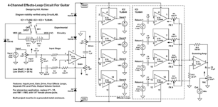
First is a 4-channel effects-loop diagram which I suggest as a primary controller. It features Input Level and Input Gain controls plus a Drive control sending the boosted input signal to four non-inverting buffers whose outputs, Send 1 through Send 4, would go to the inputs of four different preamps (or effects, etc.). No separate level controls are included for the Sends since my preamps (or whatever effects or other gear is used has volume controls of their own), but level controls are used on the buffered return channels, whose signals are mixed in the Summing Amp. Note: The summing-amp circuit can be used as a separate 4-channel mixer, independently of the rest of this circuit. Also, not all four channels must be used. Only those for which a user has use should be employed, this while keeping unused channels as spare, auxiliary, or extra channels, available if needed (e.g., a direct signal).

I retained the input and output symbols required by the CircuitLAB Editor, in which I drew theses designs, but it’s easy to see how these symbols can be changed to ordinary 1/4 “ phone jack symbols, as shown here.

Next is a 4-channel quiet-switch circuit for enabling / disabling any given loop separately.

Patch the four Sends from the effects loop circuit into the four Inputs of this quiet switcher, whose outputs then go to four separate preamps, effects, etc., and whose own outputs are in their turn patched to the Returns of the effects loop circuit. And here again, not all four channels need to be used. Any given channel is only enabled when its latching Push-On / Push-Off footswitch has been pushed On. Otherwise, the channel is inactive. And for LEDs to indicate active channels, use LEDs in parallel with the Pop Eliminators, as shown below; one LED Circuit per Pop Eliminator (i.e., 4 required).

Alternative to independently enabled / disabled channels, there is the following 1-of-4 Exclusive Selector Circuit, for those who want to be able to push one footswitch to enable one loop at a time while all the others are automatically disabled.

I recommend building one each of the 4-Channel Effect Loop and the 4-Channel Quiet-Switch circuits and use them together to get four channels with separate enable / disable switches. Then build two 1-of-4 Exclusive Selector Circuits and use them on two of the primary channels, leaving the other two primary channels available for other devices. This will give the user control of ten different devices -- four exclusively selectable between each other, plus four others exclusively selectable between each other, with two separately enabled / disabled channels controlled by the 4-Channel Quiet-Switch circuit.
Note: Despite their names, both of the above two diagrams involve quiet switching.
I also recommend assigning at least one channel of the Effect Loop circuit for the direct signal, perhaps not using a preamp or effect in that channel, but rather connecting the Send and Return with a patch cable, or else using a clean boost in that channel. Then the direct signal can be mixed as desired with the other signals in the Summing Amp. This will not necessarily alter the other signals but will ensure that the unaltered direct signal is retained while the other signals are emphasized as needed, with a view to obtaining the proper difference between clean, crunch, fuzzed or other sounds while playing live, and also having the ability to switch between the various sounds without any popping noises disturbing the transitions between the different sounds.
Now we look at a clean A / B Switching Circuit, which can double as a bypass switcher if one channel’s Send and Return are connected with a patch cable, while the other has a preamp, effect, effects-line, or processor. In this case, we combine an exclusive selector circuit with a unity-gain preamp driving the two channels. The outputs of whatever is used in the two channels is then mixed (though without separate level controls) in a summing-amp whose output is sent to the top of the Volume control.
Here, let’s suppose we need to switch live between two effects, as an example of how this circuit works. There are no tone controls since those will either be included in the effect circuits or can be added between the effects outputs and the Return jacks of this circuit, or a tone-control circuit can otherwise be used on the output of this circuit. In any case, note that this circuit can be used to select between Effect A or Effect B, but can also combine the outputs of A+B together. And here too, if a builder wants indicator lights for each case, the LED circuit given above can be incorporated with the Pop Eliminators.

As indicated in the foregoing Selector circuit, the CD4050 hex non-inverting buffer (IC2 above) is used as a delay device for the clock-pulse. This is necessary because without it depressing one of the DPDT momentary footswitches would cause both the Clear and the Clock inputs to be changed simultaneously, but the Clear pulse takes precedence. We want the Clear to initiate before the Clock pulse arrives at its input to IC1, so the Clock pulse must be delayed. Thus, the Clear will turn off all the flip-flops in IC2, but then the Clock pulse arrives soon afterwards, at which time (assuming it takes a few fractions of a second for the footswitch to be pressed) one of the footswitches will be sending a +5V DC control voltage to the CD4066 quad bilateral switch IC, turning on either one or two of the bilateral switches, as the case may be. If SW1 is pressed, it will activate the bilateral switch at the output of Channel A, while pressing SW2 activates the bilateral switch at the output of Channel B, and Channel A is turned off. But if SW3 is pressed, then two other bilateral switches, one for Channel A and the other for Channel B, will be activated. And because we are using an exclusive 1-of-3 selector circuit as the controller, the bilateral switches assigned for the separate translations of the A and B signals will be deactivated.
Note, however, that there is a Clear switch, which can be used to disable both channels at the same time, thus shutting down the entire circuit, but without cutting power. That could be useful if the user has the direct or other signals going by another way, or it can be used as a mute button. Placement of that switch, therefore, depends on how it is to be used. Perhaps, in any event, it should be placed so that it cannot be activated accidentally.
Return our attention to IC2, the jumpers on the non-inverting buffers determine the amount of delay that is imparted to the Clock pulse. Each buffer gives about 45 ns (nanoseconds) of delay, so the total would be about 270 ns. Don’t worry if that can be heard. It’s too fast for the human ear to detect. For instance, the shortest delay a digital delay effect will go to is 1 ms (millisecond), which cannot be heard as differing from the original input signal. It takes 30 to 50 ms to make such a device sound like it’s providing a doubling effect, at best. So, even at a maximum Clock pulse delay of 270 ns, that’s still several orders of magnitude faster than the fastest delay a digital delay effect can produce. Yet, it is not certain how much of a delay is needed for the Clock pulse. That is why the jumpers are experimental.
Craig Anderton has a quiet switch circuit that uses a delay tactic like this, but employs diodes and capacitors to get the delay, and which only causes the Clear pulse to be wider than the Clock pulse, though delaying the Clock pulse’s leading edge just enough (as indicated graphically in the datasheet for the quad flip-flop IC). That works well, according to Anderton, but I did not want to copy his design, so I came up with one of my own. And as can be seen, mine allows for a much longer delay time for the Clock pulse than would be obtained with diodes and capacitors, as compared to non-inverting buffers. Also, I have also seen a delay circuit for a TV sound surround system that uses dual op-amp ICs to get analog delays of audio signals. Of course, it required the use of many such ICs, with the op-amps connected in series, but it was a proven circuit, used in well-regarded brand-name TVs until being replaced by digital delay circuits in more recent times. The point is that those jumpers will have to be experimented with to see if the 270 ns delay is enough, or if the amount of delay should be shortened (by bypassing some jumpers), or if it’s not enough (at which yet another hex buffer should be added). I suspect that three of the buffers would be adequate, but only actual testing of a breadboarded circuit will provide that answer, although I am fairly certain the design will work properly as is (assuming the time a footswitch is pressed is on the order of milliseconds, not microseconds or nanoseconds).
The power supply for the Effect Loop circuit must be a regulated split-polarity +-9V DC supply, but the other circuits need only the positive voltage from that supply. Here's an example. This type of supply would be sufficient to supply all the above circuits simultaneously.

The wall plug is not shown. Use a 3-prong and connect the ground lug to circuit ground. Also, for an illuminated power switch, consider the following example from Parts Express: Round Rocker Switch, illuminated, part # 060-716. www.parts-express.com $1.99
EOF
To use four of my preamps or other circuits, or any set of four other preamps, stomp-box effects, effect-lines, or processors, here are some potentially useful designs. They have not been built and tested, nor verified by a simulator, but should work based on long standing design principles and applications information in the IC datasheets.
First is a 4-channel effects-loop diagram which I suggest as a primary controller. It features Input Level and Input Gain controls plus a Drive control sending the boosted input signal to four non-inverting buffers whose outputs, Send 1 through Send 4, would go to the inputs of four different preamps (or effects, etc.). No separate level controls are included for the Sends since my preamps (or whatever effects or other gear is used has volume controls of their own), but level controls are used on the buffered return channels, whose signals are mixed in the Summing Amp. Note: The summing-amp circuit can be used as a separate 4-channel mixer, independently of the rest of this circuit. Also, not all four channels must be used. Only those for which a user has use should be employed, this while keeping unused channels as spare, auxiliary, or extra channels, available if needed (e.g., a direct signal).
I retained the input and output symbols required by the CircuitLAB Editor, in which I drew theses designs, but it’s easy to see how these symbols can be changed to ordinary 1/4 “ phone jack symbols, as shown here.
Next is a 4-channel quiet-switch circuit for enabling / disabling any given loop separately.
Patch the four Sends from the effects loop circuit into the four Inputs of this quiet switcher, whose outputs then go to four separate preamps, effects, etc., and whose own outputs are in their turn patched to the Returns of the effects loop circuit. And here again, not all four channels need to be used. Any given channel is only enabled when its latching Push-On / Push-Off footswitch has been pushed On. Otherwise, the channel is inactive. And for LEDs to indicate active channels, use LEDs in parallel with the Pop Eliminators, as shown below; one LED Circuit per Pop Eliminator (i.e., 4 required).
Alternative to independently enabled / disabled channels, there is the following 1-of-4 Exclusive Selector Circuit, for those who want to be able to push one footswitch to enable one loop at a time while all the others are automatically disabled.
I recommend building one each of the 4-Channel Effect Loop and the 4-Channel Quiet-Switch circuits and use them together to get four channels with separate enable / disable switches. Then build two 1-of-4 Exclusive Selector Circuits and use them on two of the primary channels, leaving the other two primary channels available for other devices. This will give the user control of ten different devices -- four exclusively selectable between each other, plus four others exclusively selectable between each other, with two separately enabled / disabled channels controlled by the 4-Channel Quiet-Switch circuit.
Note: Despite their names, both of the above two diagrams involve quiet switching.
I also recommend assigning at least one channel of the Effect Loop circuit for the direct signal, perhaps not using a preamp or effect in that channel, but rather connecting the Send and Return with a patch cable, or else using a clean boost in that channel. Then the direct signal can be mixed as desired with the other signals in the Summing Amp. This will not necessarily alter the other signals but will ensure that the unaltered direct signal is retained while the other signals are emphasized as needed, with a view to obtaining the proper difference between clean, crunch, fuzzed or other sounds while playing live, and also having the ability to switch between the various sounds without any popping noises disturbing the transitions between the different sounds.
Now we look at a clean A / B Switching Circuit, which can double as a bypass switcher if one channel’s Send and Return are connected with a patch cable, while the other has a preamp, effect, effects-line, or processor. In this case, we combine an exclusive selector circuit with a unity-gain preamp driving the two channels. The outputs of whatever is used in the two channels is then mixed (though without separate level controls) in a summing-amp whose output is sent to the top of the Volume control.
Here, let’s suppose we need to switch live between two effects, as an example of how this circuit works. There are no tone controls since those will either be included in the effect circuits or can be added between the effects outputs and the Return jacks of this circuit, or a tone-control circuit can otherwise be used on the output of this circuit. In any case, note that this circuit can be used to select between Effect A or Effect B, but can also combine the outputs of A+B together. And here too, if a builder wants indicator lights for each case, the LED circuit given above can be incorporated with the Pop Eliminators.
As indicated in the foregoing Selector circuit, the CD4050 hex non-inverting buffer (IC2 above) is used as a delay device for the clock-pulse. This is necessary because without it depressing one of the DPDT momentary footswitches would cause both the Clear and the Clock inputs to be changed simultaneously, but the Clear pulse takes precedence. We want the Clear to initiate before the Clock pulse arrives at its input to IC1, so the Clock pulse must be delayed. Thus, the Clear will turn off all the flip-flops in IC2, but then the Clock pulse arrives soon afterwards, at which time (assuming it takes a few fractions of a second for the footswitch to be pressed) one of the footswitches will be sending a +5V DC control voltage to the CD4066 quad bilateral switch IC, turning on either one or two of the bilateral switches, as the case may be. If SW1 is pressed, it will activate the bilateral switch at the output of Channel A, while pressing SW2 activates the bilateral switch at the output of Channel B, and Channel A is turned off. But if SW3 is pressed, then two other bilateral switches, one for Channel A and the other for Channel B, will be activated. And because we are using an exclusive 1-of-3 selector circuit as the controller, the bilateral switches assigned for the separate translations of the A and B signals will be deactivated.
Note, however, that there is a Clear switch, which can be used to disable both channels at the same time, thus shutting down the entire circuit, but without cutting power. That could be useful if the user has the direct or other signals going by another way, or it can be used as a mute button. Placement of that switch, therefore, depends on how it is to be used. Perhaps, in any event, it should be placed so that it cannot be activated accidentally.
Return our attention to IC2, the jumpers on the non-inverting buffers determine the amount of delay that is imparted to the Clock pulse. Each buffer gives about 45 ns (nanoseconds) of delay, so the total would be about 270 ns. Don’t worry if that can be heard. It’s too fast for the human ear to detect. For instance, the shortest delay a digital delay effect will go to is 1 ms (millisecond), which cannot be heard as differing from the original input signal. It takes 30 to 50 ms to make such a device sound like it’s providing a doubling effect, at best. So, even at a maximum Clock pulse delay of 270 ns, that’s still several orders of magnitude faster than the fastest delay a digital delay effect can produce. Yet, it is not certain how much of a delay is needed for the Clock pulse. That is why the jumpers are experimental.
Craig Anderton has a quiet switch circuit that uses a delay tactic like this, but employs diodes and capacitors to get the delay, and which only causes the Clear pulse to be wider than the Clock pulse, though delaying the Clock pulse’s leading edge just enough (as indicated graphically in the datasheet for the quad flip-flop IC). That works well, according to Anderton, but I did not want to copy his design, so I came up with one of my own. And as can be seen, mine allows for a much longer delay time for the Clock pulse than would be obtained with diodes and capacitors, as compared to non-inverting buffers. Also, I have also seen a delay circuit for a TV sound surround system that uses dual op-amp ICs to get analog delays of audio signals. Of course, it required the use of many such ICs, with the op-amps connected in series, but it was a proven circuit, used in well-regarded brand-name TVs until being replaced by digital delay circuits in more recent times. The point is that those jumpers will have to be experimented with to see if the 270 ns delay is enough, or if the amount of delay should be shortened (by bypassing some jumpers), or if it’s not enough (at which yet another hex buffer should be added). I suspect that three of the buffers would be adequate, but only actual testing of a breadboarded circuit will provide that answer, although I am fairly certain the design will work properly as is (assuming the time a footswitch is pressed is on the order of milliseconds, not microseconds or nanoseconds).
The power supply for the Effect Loop circuit must be a regulated split-polarity +-9V DC supply, but the other circuits need only the positive voltage from that supply. Here's an example. This type of supply would be sufficient to supply all the above circuits simultaneously.
The wall plug is not shown. Use a 3-prong and connect the ground lug to circuit ground. Also, for an illuminated power switch, consider the following example from Parts Express: Round Rocker Switch, illuminated, part # 060-716. www.parts-express.com $1.99
EOF
Attachments
Last edited:
About the first schematic in post #1:
1) What is driving IC2a, IC2c and IC2d?
2) What happens when the wiper of R8 (or R9, or R10, or R11) is set to minimum level? Does this not short all the channels to ground?
1) What is driving IC2a, IC2c and IC2d?
2) What happens when the wiper of R8 (or R9, or R10, or R11) is set to minimum level? Does this not short all the channels to ground?