Hey Vunce,Hi redjr,
I’ve got something for you to try.
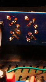
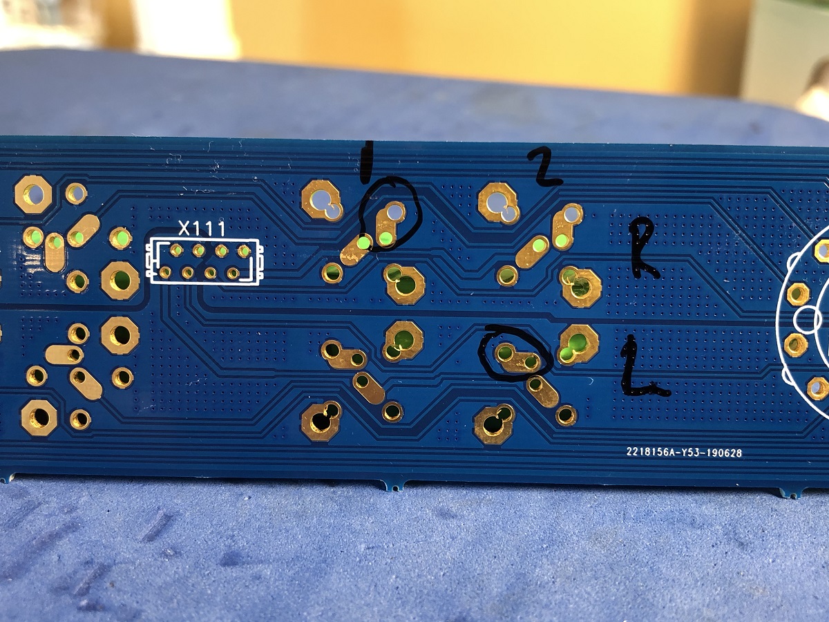
Solder a jumper wire as per my markup of your I/O panel for the two output RCA’s.
That will fix the ungrounded outputs.
Thanks for the tip. During my troubleshooting this afternoon, and once I figured out what-was-what on the back of the jacks, I realized I could strap those points and ground the jack. While that's a stop-gap approach, and I may well do it, I'd like to know why those particular jacks are wired that way. Seems to me there must be a valid reason, unless they are defective. (2 not likely) Either way, I'm somewhat surprised no one else ran into this issue. Now that I know only one jack is grounded, I will use that jack for my sub.
Also, if we 'know' the reason, it would be helpful information to someone else building this pre down the road. It sure caused me some headache today! I'm curious if this grounding is an issue with other style jacks. If it is, it would seem to me to be a PCB design decision.(?) I guess no one is using a sub - at least with these jacks in this configuration.
Hi redjr,
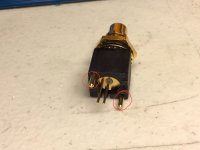
Your RCA jacks are not defective. The heavier gauge pins on the RCA jack are for support purposes only and have no electrical connection. You can actually remove those pins and install them in the vacant holes on the side and bend the GND and signal pins 90° to fit in the cut grooves to use these jacks as a right angle mount. The circled pads where the ground pin solders on the I/O board are not connected to the X111 header. But it’s complementary output ground pad is. So connecting a “stereo” amplifier or a Y-adapter cable would have one ground pad connected to the X111 header and all would be fine.
You are probably the first builder to try a set of outputs with a mono cable and happened to use the un-grounded output.
The work-around for those two locations would be to solder a jumper wire between the GND pin and either of the fat support pin pads (they also make connections to the X111 header gnd pins)
Attachments
That explains a lot.Hi redjr,
Your RCA jacks are not defective. The heavier gauge pins on the RCA jack are for support purposes only and have no electrical connection. You can actually remove those pins and install them in the vacant holes on the side and bend the GND and signal pins 90° to fit in the cut grooves to use these jacks as a right angle mount. The circled pads where the ground pin solders on the I/O board are not connected to the X111 header. But it’s complementary output ground pad is. So connecting a “stereo” amplifier or a Y-adapter cable would have one ground pad connected to the X111 header and all would be fine.
You are probably the first builder to try a set of outputs with a mono cable and happened to use the un-grounded output.
The work-around for those two locations would be to solder a jumper wire between the GND pin and either of the fat support pin pads (they also make connections to the X111 header gnd pins)
My 22v Talema’s are installed, but I did test a Talema 70064K (18v) transformer with the Qmodo jig for the Yarra and came up with:
Cs: 0.15uF
Cx: 0.01uF
Rs: 24R
Yarra snubber location ID’s
Cs = C153,154,173,174
Cx = C151,152,171,172
Rs = R153,154,173,174
I don't own an oscilloscope. I followed the annotated BOM someone had posted a long time ago and it seems like my values are way too high compared to the values others have come up with. I have 15 volt transformers and I used 2.2 uF caps at all 8 locations, and 51R resistors.
What in effect am I doing to the performance of my Yarra with these values?
I am using the stock BOM values. Unless you have and Oscope and a Quasimodo jig - it’s not essential to get a perfectly cricitcally damped pulse from the diode switch. Especially at the currents we are dealing with here.
I'll take them Al, hit me up with a number and paypal.
JT
Sorry, I missed this post. Just PM me your address and I'll send them.
I've been following redjr's grounding issue and while I'm still collecting parts I'm wondering why the I/O board has ground connections for just one channel, left I think?
My objective with this pre is to drive my pair of F4's. Am I going to to bodge in ground links on the I/O board to give both mono blocks signal ground?
My objective with this pre is to drive my pair of F4's. Am I going to to bodge in ground links on the I/O board to give both mono blocks signal ground?
My sense of the grounding issue was perhaps by design - thinking that both sets of pre-OUTs would be used for a stereo signal. If that was the case, then having ground return present on both output jacks (R & L) would have possibly created a ground loop with the connected device(s). However, without the mod shown by Vunce (a few posts back), you would have to pick the correct (GND) jack to use with a sub - or any other single channel amp. I don't think X, or JPS64 have weighed in on this topic, and why the output jacks were grounded in such a way.I've been following redjr's grounding issue and while I'm still collecting parts I'm wondering why the I/O board has ground connections for just one channel, left I think?
My objective with this pre is to drive my pair of F4's. Am I going to to bodge in ground links on the I/O board to give both mono blocks signal ground?
Just my take.
I am not sure I am understanding the issue you guys are having with the grounding scheme on the Yarra. The design philosphy was to make a monoblock preaamp with left and right channels with their own power supplies and ground planes. You can see that the left and right ground planes are split down the middle of the board where the red line is. This split continues on the volume pot board and all the way to the I/O board. The separation between ground on left and right channels is kept the whole way. The only time they would be connected is if one uses a common ground headphone jack (like I do) or a common ground RCA jack (like I do) and then the grounds are connected at the 4-connector pins, making for a rather large ground hub indicated by the light blue circle.
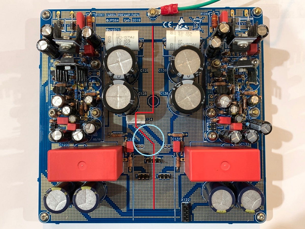
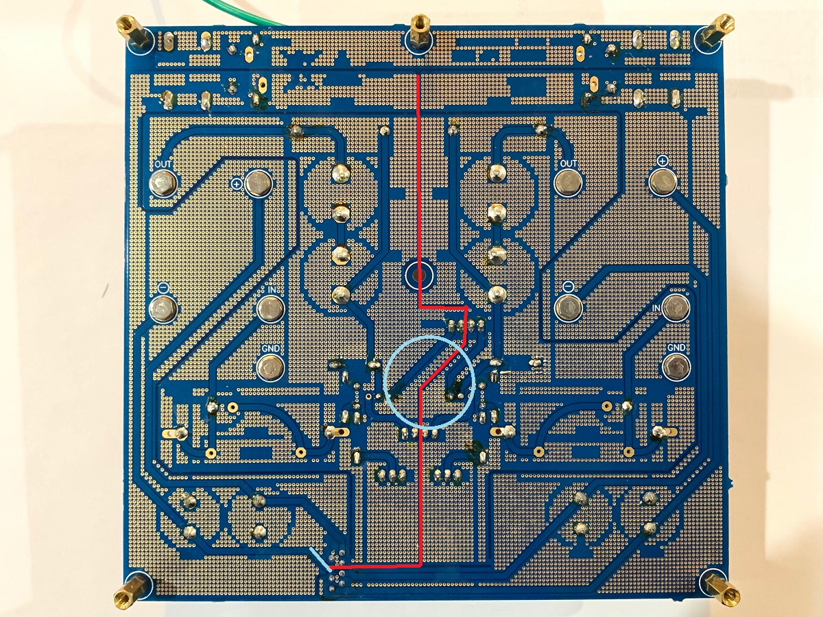
So, knowing that JP designed the layout to be a true monoblock left and right (even though in one box), would explain why if you connect an input into the left channel and expect the output on the right to also have a common ground, that won't be the case if no input jack with same ground is connected to the right channel.
So, this is why Vunce showed the mod to tie the two ground planes together if you are only feeding the left channel and expect to take the second output out of the right channel, and vice versa.
I hope this makes it more clear why the ground planes are separated.
Attachments

Edit to above post...
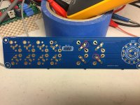
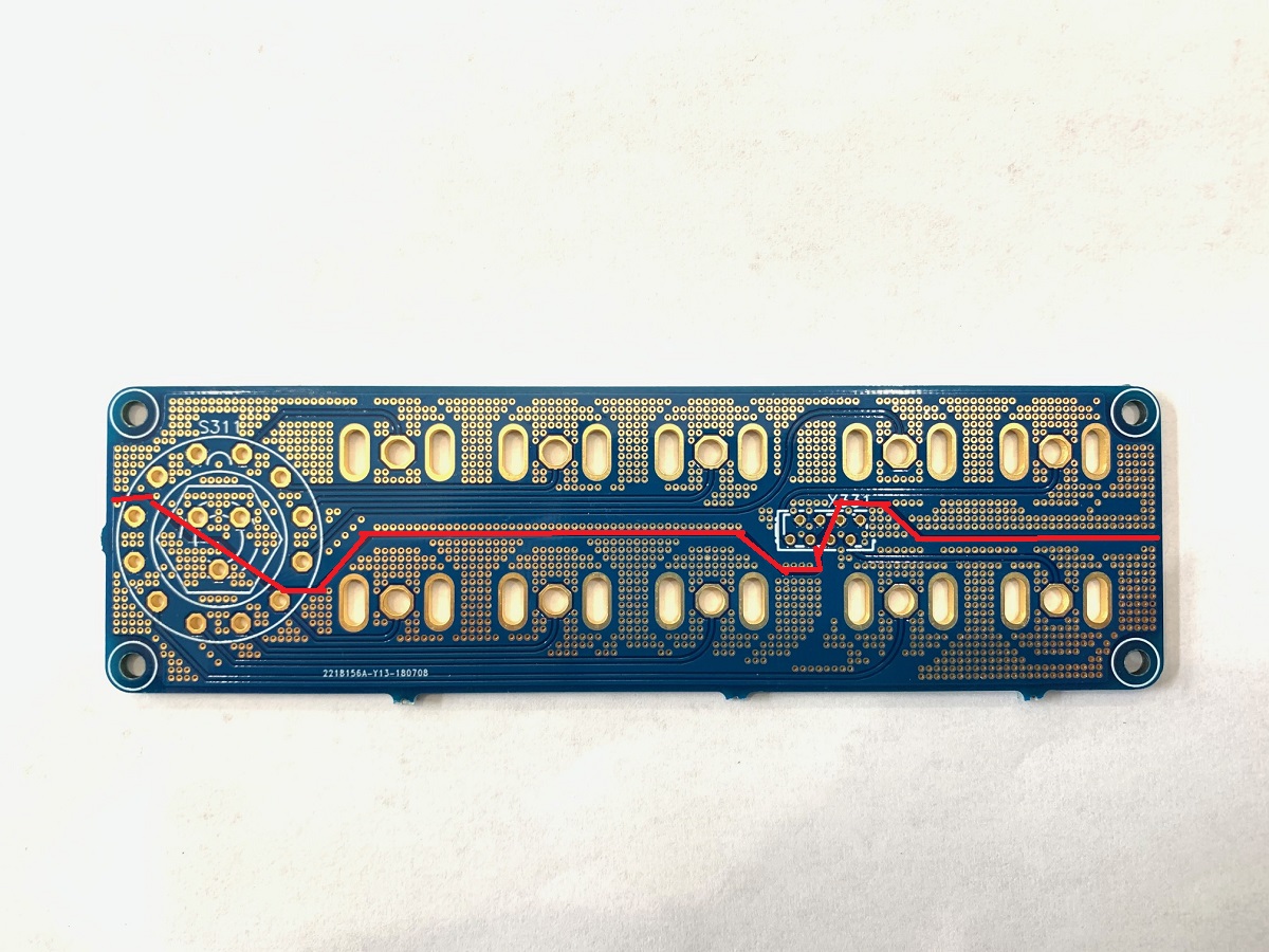
Vunce reminded me that the board I have (prototype) is different than the final production tented vias board. These seem to have orphaned ground pads circled as shown in photo from Vunce. We will look into this. For now it looks like fix is to solder a jumper "white wire".
Here is the "white wire" correction that needs to be applied (per JPS64):
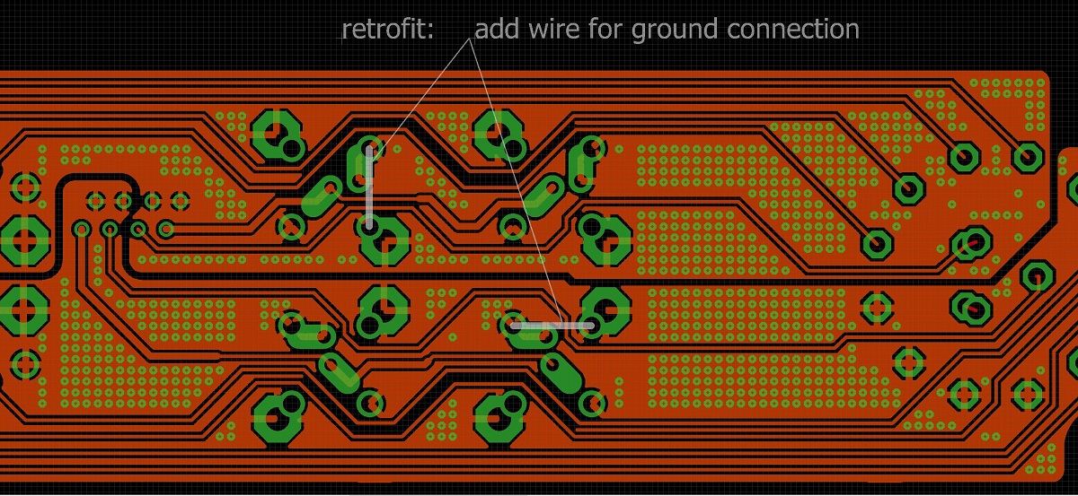
Our apologies to builders for us not catching this earlier!
Vunce reminded me that the board I have (prototype) is different than the final production tented vias board. These seem to have orphaned ground pads circled as shown in photo from Vunce. We will look into this. For now it looks like fix is to solder a jumper "white wire".
Here is the "white wire" correction that needs to be applied (per JPS64):
Our apologies to builders for us not catching this earlier!
Attachments


Last edited:
I used a different RCA socket from the BOM, so I did some continuity checks and make sure I solder to the correct ground tabs. No issues for me.
My ground loop issue(solved) was due to the star nuts shorting the VIA.


My ground loop issue(solved) was due to the star nuts shorting the VIA.
Thanks X, I see now why I wasn't seeing a connection when doing the continuity test. I can work around this now I know what's going on. Thanks
The only time my wife ever said I looked old was when I was soldering the Melbourne's. 4x magnifiers with built in floodlights.
The only time my wife ever said I looked old was when I was soldering the Melbourne's. 4x magnifiers with built in floodlights.
😎 If you haven't done a project yet, go to something like the AC/Amp Camp, do not start here. No, it's not rocket science, but only because these guys have made it possible for laymen. Is this your first project? NO!
@al Obviously, I mean knew guys/gals like me, this is not a starter project. BTW thanks for the help and insight Al
JT
Last edited:

- Home
- Group Buys
- The YARRA Preamplifier/HPA for Melbourne DB Group Buy