Without Prejudice
I have just tried to read this thread from page one to here and to be brutally frank its is shocker and a disgraceful mess for anything to be vaguely representing diy audio.
As the instigator of the original active crossover thread and catalyst for Greys involvement following Mr Pass's blessing I would like to call a motion that all irrelevant posts, be it thread jacking silly graphics or just plain dumb trouble making be wiped by the moderators.
Thankyou for listening
Ian Mackenzie
😱
Attachments
the whole truth about Sallen Key
Dear Grey,
unfortunately this is not the whole truth!
You must take into account that the TI knowledge base regards
Sallen Key filters only as the standard unity gain non inverting
topology. In this very special case it is true that a balanced
topology is not possible because of the lack of a second feedback
node.
If you choose the classical Sallen Key filter with equal components
(-> Don Lancaster "Active filter cookbook") it is not only easily to
design but also very elegant and simple.
IMHO multiple feedback arrangements of every kind are NOT
recommended at all.
You simply have to listen to such a circuit then you will know why.
Uli
GRollins said:.
-- I gather that he's concerned about my statement that the S-K topology isn't appropriate for a balanced circuit, whereas a multiple feedback filter is. Since Fred seems to prefer Revealed Truth from an Authority, let's ask Texas Instruments. I trust that they will serve as a suitable Authority for our current purposes. I quote from "More Filter Design on a Budget," SLOA096: "Fully differential modification is easily accomplished by duplicating the feedback path for the MFB topology. It is not possible for Sallen-Key topology." MFB stands for multiple feedback, in this case. They're talking about low pass filters, but the phrasing for high pass filters is identical.
Dear Grey,
unfortunately this is not the whole truth!
You must take into account that the TI knowledge base regards
Sallen Key filters only as the standard unity gain non inverting
topology. In this very special case it is true that a balanced
topology is not possible because of the lack of a second feedback
node.
If you choose the classical Sallen Key filter with equal components
(-> Don Lancaster "Active filter cookbook") it is not only easily to
design but also very elegant and simple.
IMHO multiple feedback arrangements of every kind are NOT
recommended at all.
You simply have to listen to such a circuit then you will know why.
Uli

macka said:Without Prejudice
I have just tried to read this thread from page one to here and to be brutally frank its is shocker and a disgraceful mess for anything to be vaguely representing diy audio.
As the instigator of the original active crossover thread and catalyst for Greys involvement following Mr Pass's blessing I would like to call a motion that all irrelevant posts, be it thread jacking silly graphics or just plain dumb trouble making be wiped by the moderators.
Thankyou for listening
Ian Mackenzie
😱
As to your request, I cleaned the original thread. Any additional, off topic coments please post here http://www.diyaudio.com/forums/showthread.php?s=&threadid=23331
If you don't like this arrangement, please let me know and we can improve on it.
jh6you,
Hopefully, we all try to enjoy life on a daily basis. Thanksgiving is, broadly speaking, an eating festival. Although the occasion has some putative historical basis, it's always appropriate to be glad that you've got a full stomach, no matter where you live. Go for it.
macka,
Thanks for the call for housekeeping.
uli,
That's the problem with Revealed Truth. There's always at least one loophole; frequently so many that the whole thing begins to resemble Swiss cheese. I prefer to prod around in corners and see what I can find. You end up finding a lot of dust balls, and sometimes re-invent the wheel, but every once in a while, you find something useful.
As for the pros and cons of multiple feedback filters, I haven't reccommended them per se, but they are quite useful for higher Q circuits. Now, high Q circuits carry their own burden, in that the more you ask a circuit to twist the original signal, the more likely you are to find that your signal has been phase shifted when it comes out the back end. If you want the Q, Sallen-Key isn't necessarily the best choice.
The reason I quit fiddling with X opamps (which is what I assume you have in mind for the dual output opamp in the schematic) is the DC offset problem. I've got enough trouble with slight mismatching between the 2N5457s I'm using now. I've quit trying to shoot myself in the foot, at least until I can get some sort of proper dual JFETs to work with. Yes, I could cap-couple everything, but that's not an elegant solution.
Peter,
Thanks for the cleanup.
Did I miss anybody?
Grey
Grey...
I am already using a bi amped system using an L/C filter infront of a BOSOZ pre-amp. The inductor is 1 henry and I have to use a 5k damping risistor to damp out the resonant peak. This resistor puts a load on the DAC which does not have a much of an output buffer.
I wonder if I can implement a 2 pole active filter using the BOSOZ as the op-amp??? and would this be better than using the L/C filter in front of the BOSOZ???
Is there any problem using a Ferrite core inductor as in my above mentioned L/C filter?? I am wondering about ringing or other problems....
coupling
Grey,
you are right, cap coupling is not that elegant except in the
hipass
My dc coupled X achitecture (mostly your design) is dc stable
to about 5mV (the amps are finished, the breadboarded design is
on my table for tweaking) and I am pretty optimistic that man
can handle this offset problem.
I do not wat to keep the circuit too simple. Having 6 poweramps
is not that simple either, therefore I don´t count parts anymore.
Uli
GRollins said:
The reason I quit fiddling with X opamps (which is what I assume you have in mind for the dual output opamp in the schematic) is the DC offset problem. I've got enough trouble with slight mismatching between the 2N5457s I'm using now. I've quit trying to shoot myself in the foot, at least until I can get some sort of proper dual JFETs to work with. Yes, I could cap-couple everything, but that's not an elegant solution.
Grey
Grey,
you are right, cap coupling is not that elegant except in the
hipass
My dc coupled X achitecture (mostly your design) is dc stable
to about 5mV (the amps are finished, the breadboarded design is
on my table for tweaking) and I am pretty optimistic that man
can handle this offset problem.
I do not wat to keep the circuit too simple. Having 6 poweramps
is not that simple either, therefore I don´t count parts anymore.
Uli
audionut,
I'm not clear on whether the inductor is part of the crossover or an attempt to tame a rowdy digital front end. Capacitors are cheaper and better for most audio purposes. If possible, avoid iron core inductors.
The BOSOZ can be used as an opamp, but it's not an 'ideal' one and the crossover points may end up being slightly different than calculated. Judicious substitution of resistor/cap values will get the job done, but it will take a little more effort on your part.
You won't be able to use just one BOSOZ as an opamp in a biamped system. It will take at least four channels' worth (left & right tweeter and left & right woofer) just for the crossover. Then you'll still need a preamp.
Incidentally, I'll be glad to post the artwork for the boards I'm using if anyone wants it. The problem is that the 2N5457 pinout is DSG, whereas the 2SK389 is a dual JFET DGSxSGD. The 2SK170 is DGS. In other words, my artwork won't work for the logical candidates for JFETs. If anyone has a good DSG JFET in mind, say so, and I'll post. Otherwise, I'm reluctant to go to the trouble, since the software I use for schematics puts out very large BMP files which I then have to mess with for ages in order to cut them down to size and convert them into something that will post here.
Grey
Grey, me - and maybe some people else - will try with the suboptimal JFets, because the better ones are expensive. Please post.
Resizing and converting the file is easy, use for instance http://www.irfanview.us/
Resizing and converting the file is easy, use for instance http://www.irfanview.us/
Re: the whole truth about Sallen Key
Agreed on two counts: It's a great book, especially for beginners
and high Q filters are not to my taste (except as bass equalizers)
uli said:(-> Don Lancaster "Active filter cookbook") it is not only
easily to design but also very elegant and simple.
IMHO multiple feedback arrangements of every kind are NOT
recommended at all. You simply have to listen to such a circuit
then you will know why.
Agreed on two counts: It's a great book, especially for beginners
and high Q filters are not to my taste (except as bass equalizers)
Grey
Thanks for your reply to my last question...I am using four channels of BOSOZ for the preamp in my bi-amped system...from your reply, I will replace the L/C filter in front of the BOSOZ's with the active filters we have been talking about here...Can I tap into the 60 volt rails that I am using for the BOSOZ channels to power the discrete op/amps in the active filters??? Thanks for your work on all of this...
Thanks for your reply to my last question...I am using four channels of BOSOZ for the preamp in my bi-amped system...from your reply, I will replace the L/C filter in front of the BOSOZ's with the active filters we have been talking about here...Can I tap into the 60 volt rails that I am using for the BOSOZ channels to power the discrete op/amps in the active filters??? Thanks for your work on all of this...
@ all
Which amps will you use for your new active xover project ? ? ?
If you look at the Pass active speaker, you will see that it does not contain 150W XAs, but very high efficiency speakers.
Active xover plus ClassA amps can run you in big heat trouble
Better join this thread:
http://www.diyaudio.com/forums/showthread.php?s=&threadid=22970
Re: @ all
hmm.. 350W is still a considerable amount of heat...per channel.
Maybe this auto-shutoff option is something for you, Bernhard?
/Hugo 🙂
Bernhard said:
If you look at the Pass active speaker, you will see that it does not contain 150W XAs, but very high efficiency speakers.
Nelson Pass said:
Since you have expressed interest, it looks like Rushmore
will ship with 3 X 10 watt SE Class A amps and a 50 W
Aleph X. It draws about 350 watts / ch, and we have included
an auto-shutoff option which unbiases it after 1/2 hour
without signal to save energy.
hmm.. 350W is still a considerable amount of heat...per channel.
Maybe this auto-shutoff option is something for you, Bernhard?
/Hugo 🙂
Active xover plus ClassA amps can run you in big heat trouble
But with those very high efficient speakers there is no need for complex power safeing amplifiers. With the right speakers you could be perfectly happy with 5W each for the tweeters and mids. Little more for bass.
I use Zen V4 at the moment and active xo would bring me to Zen V4 + Zen lite, or maybe a small Alephx.
till,
I'll try to start getting the board layouts up in the next day or two. There's nothing so time-consuming for me as something that will "only take five minutes." It invariably ends up taking an hour for one reason or another, and hours I ain't got.
audionut,
The BOSOZ rails can be used for the crossover, assuming that you've got surplus current available in the power supply. The caveat being that you won't be able to use the active devices listed so far. Offhand, I can't think of a JFET that is good for 60V rails, but there's no reason in the world that you can't use a decent bipolar. You could do worse than to use the MPSA42/92. Zetex will, I'm sure have a higher voltage part than the ZTX450/550 that will do just fine. Etc. Just choose your active devices wisely and you'll be fine. Fooey...what am I talking about...just use more MOSFETs: IRF610s & IRF9610s. Peachy. It'll work great.
Bernhard & Hugo,
We are DIY. We scoff at class A heat dissipation problems. More heat sinks, Igor!
Or go water-cooled, like I did. Not so good for tubes, but works like a champ for solid state.
Besides, winter is coming and I get cold down here in the dungeon.
Turn on the system, Igor!
till again,
For better or worse, I use somewhat inefficient drivers. They sound wonderful, but take a fair amount of power to get going. I've got a Mini-Rushmore-esque project that I'll be getting to in the near future (already got a name picked out). Somewhat more efficient drivers than my main system; much cheaper and more easily available than trying to lay hands on a pair of Magneplanar ribbon tweeters. In fact, many people already have these drivers on hand. Just need to take time to cut the MDF and make one decision regarding how I want to handle the low end. Easy, right? Huh! Means I'll actually get done around the year 2020 if I'm lucky.
Grey
Re: Part two of two
Hi,
Did you in the meantime check your scribblings? Is it MQ=0.63 or not? My simulations show that MQ=0,707.
Regards
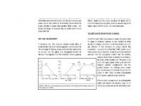
GRollins said:Nelson has three settings for Q on the XVR1: Low, Medium, and High. If my scribblings are correct, these correspond to Qs of .5, .63, and 1.......The .63 figure that Nelson appears to use for the XVR1 is a good compromise between the two, allowing for flat response with little phase shift.
Hi,
Did you in the meantime check your scribblings? Is it MQ=0.63 or not? My simulations show that MQ=0,707.
Regards
I forgot you were designing boards!!! Oh boy!
How about a group buy after we find out how it works?
How about a group buy after we find out how it works?
Grey,
Without any notion of disrespect, I am begining to wonder what you are proposing by way of board layouts for this thread.
On careful reading of all previous posts you have subsribed to the description of a variable crossover design using discrete passive filter elements rather than resistive matrix and have eluded the inclusion of the opamp or buffer being discrete or otherwise.
"The buffers can be more opamps, or even just followers, if you like. It's that simple. Anyone who tries to mystify it above and beyond that has an agenda, and it ain't Truth."
I doubt if Borbely would agree with that quote and in any case opimisation of a stable unity gain buffer suitable by design for active filters may well be beyond the means of many members without access to expensive test equipment.
Also, given the simplicity of the filter in itself and scant number of parts involved, I fail to see how you can hint at a pcb layout without inclusion of the buffer by design and best practise.
On reading your above quote the filters may as well be point to point layout, but without a layout to include the buffers the project is rather an academic exercise and a lame duck.
Rather than skirt around the issues of re engineering a current Passlabs design, would it not be approriate to offer a layout with a generic buffer option such as a follower or two stage opamp tested and ready for those interested to plug and play.
I appreciate you are short of time, but members who have followed your posts also deserve continuity of this thread.
Grey, if you prefer not to conclude the exercise with the completeness it deserves, as an alternative then members who are keen to purse a working design of thorough engineering and excellent performance would be wise to consider the Borberly All Fet Crossover at this link:
http://www.borbelyaudio.com/allfetxo.htm
Ian
- Status
- Not open for further replies.
- Home
- Amplifiers
- Pass Labs
- The Xenover