I would hope that anyone selling an enclosure would make it explicitly clear IF it is a momentary switch. I would be quietly confident in this case it isn't a mom.
There are plenty of circular push buttons with mains rated DPDT switch and an LED. They won't be high current switches but they will be plenty for a headphone amp.
There are plenty of circular push buttons with mains rated DPDT switch and an LED. They won't be high current switches but they will be plenty for a headphone amp.
I pulled out the power switch from my front panel.
It's a defond 6a 125vac - it has 3 tabs on it.
I should be able to wire it up directly to ac.
It's a defond 6a 125vac - it has 3 tabs on it.
I should be able to wire it up directly to ac.
If it has 3 tabs only the illumination is almost certainly a neon bulb. Mains switches with a neon lamp almost always have an internal protection resistor and that would allow you to wire the third tab (for the lamp) directly to Neutral of the incoming ac without the need of extra components.
Ok. I'm using the middle and top tab. It seems to power up ok.
But since swapping out the jack, I seem to have a few touchy issues with the output.
I'll have to open it up to take another look at it.
But since swapping out the jack, I seem to have a few touchy issues with the output.
I'll have to open it up to take another look at it.
Owen (or anyone else who knows), what's the pitch for the input and output vias on the PSU board? By comparing to my 0.200'' pitch terminal blocks it looks like .150'', but I'd like to know for sure =)
Hi Emphrygian,
It probably is 150 but I'll confirm when I get home this evening.
Cheers,
Owen
It probably is 150 but I'll confirm when I get home this evening.
Cheers,
Owen
Owen (or anyone else who knows), what's the pitch for the input and output vias on the PSU board? By comparing to my 0.200'' pitch terminal blocks it looks like .150'', but I'd like to know for sure =)
Hi Emphrygian,
Sorry for the delay... I just checked the layout and both inputs and outputs on the PSU are spaced at 0.125".
They were intended to have wires soldered directly to the pads, so I'm not sure if they make connectors with that pitch. Next time I'll opt for a more standard spacing if there is room.
Cheers,
Owen
What would be nice is if a DAC chip were butted up to the headphone amp chips. With I²S input. So I can wire my CMedia DSP, with cross feed, into it and therefore delete analogue interconnect and all the degradation that come with it. A pal tried this with 0.5 metre and 5 metres of cheap microphone cable and could hear no difference.
I'd then want to extrapolate this to having the DAC and amps on the headphone head band with long I²S and long ± DC voltage wires. Thereby deleting the speakers cables and all the degradation that come with it.
But what DAC chip, etc.
I'm thinking of an AK4396 as they are about £5 and available and sound not too bad and have a balanced output to go into the balanced input.
Last edited:
yeah because signal integrity in long i2s wiring and long low level DC is so much more robust than long analogue interconnects....
(i2s is designed to travel mm between chips on the same PCB, it has no CMRR, it has no error correction at all)
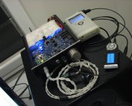
the AKM is a decent choice though, or perhaps the es9016 and modify 'the wire' to have suitable IV resistors. thats what I did with my 'portable' ES9018 + the wire BAL-BAL
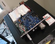
the wire is under the blue reg/battery manager/volume control/toslink+BNC input comparator/mcu PCB. It is wired directly to the es9018 dac outputs with ASMP SMD Zfoil IV resistors on 'the wire'
you can see the bling stranded UPOCC silver twisted pair outputs to a Lemo 4 pin, I do have a few long held irrational beliefs left that arent going away any time soon. I still believe in OTT build quality, magic not so much.
(i2s is designed to travel mm between chips on the same PCB, it has no CMRR, it has no error correction at all)
the AKM is a decent choice though, or perhaps the es9016 and modify 'the wire' to have suitable IV resistors. thats what I did with my 'portable' ES9018 + the wire BAL-BAL
the wire is under the blue reg/battery manager/volume control/toslink+BNC input comparator/mcu PCB. It is wired directly to the es9018 dac outputs with ASMP SMD Zfoil IV resistors on 'the wire'
you can see the bling stranded UPOCC silver twisted pair outputs to a Lemo 4 pin, I do have a few long held irrational beliefs left that arent going away any time soon. I still believe in OTT build quality, magic not so much.
Attachments
Last edited:
It's found going much further. The 1980's Philips players had it going from board to board via multiple plugs and sockets and wires. The DAC Magic that I have I think it might be the I²S that being fiddled with to create a compliment, then going through multiple vias over about 6 inches.(i2s is designed to travel mm between chips on the same PCB, it has no CMRR, it has no error correction at all)
It may or may not be ideal but analogue wire are certainly not.
When I say that a pal tried it, what I mean is that in the '90's, as a business, he was making and selling outboard PSU's with a long I²S umbilical to discerning customers. And not cheap either. It was working well enough.
I might like to use those ESS chips but I can't stretch to the expense at this time. And if I recall correctly I don't like the Buffalo boards, the layout seemed messy with so many other sub board needed. And the price...
Having said that, I just saw this post saying he has a "DIY USB DAC based on the ES9023 Sabre DAC and it only cost me £25" http://www.whathifi.com/forum/dacs/audioquest-dragonfly-dac
A friend just bought the Audioquest Dragonfly DAC I've not really heard it.
Last edited:
anywhere its found going much further without some sort of reclocking stage is likely to cause at least as much distortion as analogue interconnects, which have only anecdotal distortion at these levels if properly made. it was not designed to be used like that, but of course people still make stupid design decisions
yeah ive seen that dragonfly thing, honestly the marketing department has a lot to answer for, they make a number of ******** impossible claims, particularly about the volume control and headphone amp sections.
re buffalo I know what you mean and agree for the most part, but as you can see i've used only one small dac module. it all went a bit crazy after the buffalo II and some of the tangled messes people called dacs with the BIII are nuts. it would be difficult or impossible to do what I did above with the BIII or even BIIISE rather than the BII
Hi Emphrygian,
Sorry for the delay... I just checked the layout and both inputs and outputs on the PSU are spaced at 0.125".
They were intended to have wires soldered directly to the pads, so I'm not sure if they make connectors with that pitch. Next time I'll opt for a more standard spacing if there is room.
Cheers,
Owen
Thanks for checking.
It does indeed seem like there are no .125'' terminal blocks at Digikey and I can't be bothered to investigate more, it's not that big a deal. I'll just solder the wires directly to the pads, like you intended.
I had sort of figured I had to do this anyway, since a block would likely not fit with respect to the closeness of the ouput caps (unless I mount them on the back). Blocks on the input would have been nice, but as I said, no big deal.
Last edited:
not a huge fan of blocks myself, never use them except sometimes on power supplies. for signal CMRR is more important to me than having a block, if it needs to be able to be disconnected I put an inline connector.
not a huge fan of blocks myself, never use them except sometimes on power supplies. for signal CMRR is more important to me than having a block, if it needs to be able to be disconnected I put an inline connector.
I would never consider blocks for signals, only on voltage regs and such. Helps a lot if you want to try out different ones =)
- Home
- Amplifiers
- Headphone Systems
- "The Wire" Ultra-High Performance Headphone Amplifier - PCB's