Hi Guys,
Things are moving along pretty well, and the SE-SE version is more or less finished. I'm going to start on the BAL-BAL version tomorrow and it will likely be based on the OPA1632.
The layout on the SE-SE version turned out to be very clean, and it will also be pretty cheap to build. I get the feeling there will ultimately be a lot of interest in that particular version since people were always asking me how to connect the original version with SE inputs. When I get it a little more polished, I'll post it up here.
Which brings me to my next point: connectors
Do people prefer on-board connectors, or should I just break the inputs and outputs out to pads so people can use whatever connector they like? I'm pretty easy going either way, so if anyone has ideas, let me know.
If people prefer on-board connectors, then what is the best connector to use for the balanced output on the BAL-BAL amp? Is it the usual output standard XLR? If so, what is the generally accepted pinout?
I also can't seem to find any decent PCB mount RCA connectors, so I'm leaning towards just pads for everything. Any suggestion?
Last but not least is the regulators. Looks like qusp has a few good suggestions, so I'll read over the datasheets and see what's what.
Cheers,
Owen
Hi Qusp
for the psu i recommend looking at the lt1764a and only the lt1764a; using 2 connected in series for a bipolar supply,
I don't understand your solution to replace a LM317 and a LM337 with the lt1764a ....
Can you please give me more details ?
Thanks
Serge
for the psu i recommend looking at the lt1764a and only the lt1764a; using 2 connected in series for a bipolar supply,
I don't understand your solution to replace a LM317 and a LM337 with the lt1764a ....
Can you please give me more details ?
Thanks
Serge
I am interested in 1 set of Bal - SE pcb and parts. If there is a psu I would like one too.
With regards to connectors, I would prefer just faston connectors for all connections. That way, we could have our choice of input and output connectors. And even choice of terminating ground pin of xlr. This would increase the signal path though.
Going to be my first time soldering SMD. Will this be a good place to start?
Hi Owen,
My vote goes for one BAL-BAL type based on OPA1632.
If PSU is available, I take one.
Thanks,
Francis
My vote goes for one BAL-BAL type based on OPA1632.
If PSU is available, I take one.
Thanks,
Francis
cool, any chance you could put an optional pattern for the dgn version of the opa1632? as in soic8 and dgn right on top of each other in parallel with a via in the middle for the power pad. its got higher current capability and a better connection for vcom. plus i have a small rail of them and ths4131 in that package already 😀
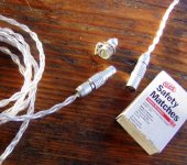
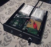
as for connectors, i like lemo or hirose hr10, the hr10 is becoming a bit of a standard for balanced headphones, as is 4 pin xlr, but i think even 4 pin xlr is a silly size for a headphone connector. i like lemo the best (see bottom attachments for it fitted to my jh13 cable and early pics of the portable sabre, but i'm probably on my own here a bit, i think everyone would agree they are the superior connector, but you wont find a headphone other than diy using one and they are a bit pricey.
the hirose hr10
and panel socket are also excellent and quite a bit cheaper, not as sexy though, or compact (though still much more compact than xlr. if not i would suggest if you could just leave it as throughole 2.54mm pitch header type connection, i could just make my pcb mount lemo above fit without putting others that arent keen on reterminating their headphones out.
as far as the regulators, tom and i actually already have a compact high perfomance smd pcb designed for the lt1764a ready, including placement for a same package smd cree zero recovery diode. so same package all the way around, all heatsinking is done to the pcb copper pour, with no need for additional heatsinking and pretty easy packages to solder. we have done all the research for the proper caps for good dynamic behavior of the regs. the lt1764a will put out up to 3A, the lt1963a will put out 1.5A and the neg reg lt1185 is 3A. all are pretty low dropout as well. the linear tech stuff has excellent and thorough datasheets and app notes, one of the reasons i love them
the price on the regs varies quite a bit depending where you get them, so a gb from digikey would be in order i think. tom and i were already planning on getting up to 50 of the regs and more of the diodes, so theres the start of a gb right there. do not try to buy at newark, or farnell/element14, they are stupid expensive there
I can ask if he minds if i send you the files to give you a head start?
as for connectors, i like lemo or hirose hr10, the hr10 is becoming a bit of a standard for balanced headphones, as is 4 pin xlr, but i think even 4 pin xlr is a silly size for a headphone connector. i like lemo the best (see bottom attachments for it fitted to my jh13 cable and early pics of the portable sabre, but i'm probably on my own here a bit, i think everyone would agree they are the superior connector, but you wont find a headphone other than diy using one and they are a bit pricey.
An externally hosted image should be here but it was not working when we last tested it.
the hirose hr10
and panel socket are also excellent and quite a bit cheaper, not as sexy though, or compact (though still much more compact than xlr. if not i would suggest if you could just leave it as throughole 2.54mm pitch header type connection, i could just make my pcb mount lemo above fit without putting others that arent keen on reterminating their headphones out.
An externally hosted image should be here but it was not working when we last tested it.
An externally hosted image should be here but it was not working when we last tested it.
as far as the regulators, tom and i actually already have a compact high perfomance smd pcb designed for the lt1764a ready, including placement for a same package smd cree zero recovery diode. so same package all the way around, all heatsinking is done to the pcb copper pour, with no need for additional heatsinking and pretty easy packages to solder. we have done all the research for the proper caps for good dynamic behavior of the regs. the lt1764a will put out up to 3A, the lt1963a will put out 1.5A and the neg reg lt1185 is 3A. all are pretty low dropout as well. the linear tech stuff has excellent and thorough datasheets and app notes, one of the reasons i love them
the price on the regs varies quite a bit depending where you get them, so a gb from digikey would be in order i think. tom and i were already planning on getting up to 50 of the regs and more of the diodes, so theres the start of a gb right there. do not try to buy at newark, or farnell/element14, they are stupid expensive there
I can ask if he minds if i send you the files to give you a head start?
Attachments
Last edited:
Hi Qusp
for the psu i recommend looking at the lt1764a and only the lt1764a; using 2 connected in series for a bipolar supply,
I don't understand your solution to replace a LM317 and a LM337 with the lt1764a ....
Can you please give me more details ?
Thanks
Serge
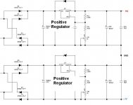
exactly what i said, use 2 x lt1764a, one set for say 12vdc and another set for 24vdc, connect the 2 outputs in series, the ground on the first 12v reg and the psu in general becomes the -12vdc, the 12v output of the same becomes 0v and the 24vdc output of the second reg becomes +12vdc. the opamps and buffers dont know any difference and neither does the balanced AC signal since it doesnt have a ground reference. you just need to make sure that the caps and regulators have well enough current capability to keep the 'ground' stiff. the 12v point becomes power supply and signal ground for this board only, it would only be of use for the bal in/out version, because in that case there is no need for the source to have its ground connected to the headamp.
its just an option, basically the same as running it from a split battery supply. the problem comes if you dont make it so the 12v 'ground' reference can sink enough current and have low enough output impedance, at all of the frequencies of interest. you can see this type of thing done with unreg dc supplies in some of the pass power amps, circlotrons come to mind its not really virtual ground but has striking similarities to it
the 1175 or 1185 will work well also as they are actual negative regs. virtual ground has got some bad press lately, but it is not inherently bad and its not quite the same thing, you just have to cover your bases properly and use chips and power sources that are capable to support the load. in this case the same type of reg that is supplying the power to the other rails is reinforcing ground, and i cannot see this amp ever needing to sink more than 36w haha.
to be safe you could use the lt1963a for the 24v and lt1764a for the 12v, meaning that the 'ground' channels current capability is double, so it would be near impossible for a problem to occur. lm317 is used like this often, but its a floating reg so it makes it easier to do at any voltage, as the chips i'm recommending have a ground pin, the higher voltage reg would see double the voltage of the lower reg, so the sum of the 2 rails point to point has to be within the common mode operating limits of the device.
linear has other solutions that will work also, such as using the lt1970 current sink/source controller to control a couple of fets, but i think that is beyond the scope of this build.
enough detail for ya?
sorry for the ramble guys
perhaps a less controversial and easier to comprehend, but still excellent option would be to use the lt1764a and lt1185 for the buffer supplies and the lm49610/reference/opamp reg for the opavp supplies. i dont mind which. the opa1632 can actually function on a single supply, i havent tested this out though.
i'm not sure i've described the above properly in language that can be understood. but hopefully you get the idea
Last edited:
can we please stick to 1206 for the important signal/feedback resistors? better range of high quality components and i can get my favorite naked smd zfoils tsmp series for those few positions
Hi qusp,
I would really argue that going to a larger package for the resistors would impact layout significantly enough that all the zfoils in the world wouldn't make up the difference.
Besides, there are 0805 sizes listed on the Zfoil datasheet. For everyone else, there are 0.01% thin film resistors from SEI here:
Digi-Key - RNCF0805TKY1K00TR-ND (Manufacturer - RNCF0805TKY1K00)
These will likely be the ones included with the kit.
Regards,
Owen
OK, that did it. 🙂 I'll have to start considering kits instead of boards. 🙂 I'll wait until the kit details and pricing are finalized before changing again though.
I've been meaning to check if 0.01% resistors are available in SMD. Apparently they are! I haven't bought all that many surface mount parts, but I use 0.1% through-hole resistors quite a bit - best tolerance I can typically get in through hole - for PS resistive dividers, op amp gain setting, op amp input offset resistors, etc. Plus they have a lower temp coefficient.
I've been meaning to check if 0.01% resistors are available in SMD. Apparently they are! I haven't bought all that many surface mount parts, but I use 0.1% through-hole resistors quite a bit - best tolerance I can typically get in through hole - for PS resistive dividers, op amp gain setting, op amp input offset resistors, etc. Plus they have a lower temp coefficient.
me said:as the chips i'm recommending have a ground pin, the higher voltage reg would see double the voltage of the lower reg, so the sum of the 2 rails point to point has to be within the common mode operating limits of the device.
just checked the DS; the lt1764a has a max vout of 20v, so this would only work up to a max of +/-10v, so just the proper bipolar supply of lt1764a/lt1185.
ok, you can switch off the qusp channel now. ive given my opinion too much of my opinion, i'll leave it to you opc.
just happens that ive done a lot of reading and playing with these regs and opamps lately. i always planned to add a buffer to the output to see how that went, so this is perfect and with the skills far above my own to design it.
night guys
Last edited:
one last answer didnt see your post.
opc, i doubt that adding 1mm to either side of 4 pads on the board will impact as you say, but yes they are available in 0805, i just prefer the 1206 with these, as they are fiddly to solder as are specified for reflow being naked and all (DS recommends against using tweazers or hand soldering, but its possible). i have a blank 'the wire' in front of me and i could just about and probably could, fit the 1206 on the 0805 pad without interfering with any other trace, or object, and i roiutinely solder 0805 to a 1206 pad if i dont have the right part. so not sure how it would cause any problem at all. but as i said i'll leave it up to you and i'll find something to fit. the vishay melf are also 1206, which are not as expensive and still foil rather than film
yep thats what i mean Sergelisses.
just checked: it actually does fit, could use 0.5mm wiggle, but i'll make it work either way
Last edited:
actually looking again i had something else in mind Sergelisses. i'll send you a pm tomorrow after drawing it up, dont want to go further along that path unless its where the design is going. i need to sleep before i send people insane (too late) with crappy punctuation
Last edited:
Hi, count me in 😉
1. Board only (maybe hard to find/source parts depends on the cost)
2. No PSU
3. Fully Balanced version
4. One Unit
Thank's
1. Board only (maybe hard to find/source parts depends on the cost)
2. No PSU
3. Fully Balanced version
4. One Unit
Thank's
I think I would be interested:
1. Full kit
2. PSU included
3. SE to SE
4. At least one, probably two units
1. Full kit
2. PSU included
3. SE to SE
4. At least one, probably two units
Hi Guys,
Layout is still progressing, and things will probably be much easier to do without any connectors on the boards.
Since several people here have voiced an opinion to get rid of the on-board connectors, I'm pretty sure that's what I'm going to do.
I'll either use a solder pad, some 0.1" header pins, or Faston.
I've updated the list with all the latest requests, so please check it over an make sure you're put down for the right item and QTY.
I'll be away for the weekend, but I'll keep everyone posted on any progress.
Thanks,
Owen
Attachments
- Home
- Amplifiers
- Headphone Systems
- "The Wire" Ultra-High Performance Headphone Amplifier - PCB's