I wonder if specifying 230V primary rating is adding to that effect. Those on the North American continent may not have the same problem, not sure how tight their distribution voltages are regulated, I expect its probably quite well regulated since they have a lot more small distribution transformers and short LV network by comparison to how grid is operated here.
Generally speaking the distribution network here is set up for 240V +/- 6% but ~260V is certainly not unheard of ... after reading this I measured line voltage at the wall on the weekend and got ~249V late Saturday afternoon.
Like you and opc have said the power supply filter caps shouldn't have too many issues with being run above rated voltage for a short period, certainly worth being aware of though!
Last edited:
do you guys actually call them crocodile clips down there?
Only the real odd balls amongst us

I wonder if specifying 230V primary rating is adding to that effect. Those on the North American continent may not have the same problem, not sure how tight their distribution voltages are regulated, I expect its probably quite well regulated since they have a lot more small distribution transformers and short LV network by comparison to how grid is operated here.
Generally speaking the distribution network here is set up for 240V +/- 6% but ~260V is certainly not unheard of ... after reading this I measured line voltage at the wall on the weekend and got ~249V late Saturday afternoon.
Like you and opc have said the power supply filter caps shouldn't have too many issues with being run above rated voltage for a short period, certainly worth being aware of though!
i'm aware we are set up for 240 for the most part and we discussed that, I actually dont see it as a real problem, but as you say best to be aware of it so I posted it here. my voltage at the wall couldnt have been too high though, wasnt up for doing that at 5am or whenever it was. with a no load specified voltage of 20.7vac we get 29.187vdc before the diode drop, which with no load isnt likely to have been more than 2v I wanted the slightly higher voltage when I specified 16v secondaries instead of 15, despite what you have told me about new solar going online etc, I up till this point have found the voltage to be LOW under times of high load and that I mostly have not in the past gotten the secondary output I was hoping for when I spec 240, risking only getting 15 out of this 16v transformer....
if I were to change anything it would be the caps
Only the real odd balls amongst us
moi? hey look i'm not the one with the urushi painted line transformers hehe
Don't get me wrong, I'm not concerned and I agree the tx spec is pretty much ideal! Agree that if anything the caps would be the place to tweak but not worth it for something that's only a concern while testing the regulators.
My point was more that on a more tightly regulated distribution network their may be less voltage fluctuations and they might not exceed the capacitor voltage spec by as much. For those in northern hemisphere that are part of the GB that is.
My point was more that on a more tightly regulated distribution network their may be less voltage fluctuations and they might not exceed the capacitor voltage spec by as much. For those in northern hemisphere that are part of the GB that is.
Last edited:
no worries yeah maybe not, but it will still go just over, I would think even the BOM transformer will.
it definitely should not should not encourage people to not build and test the regulators first, the only way for most of us to replace those buffers is by snipping the legs and thats not a cheap mistake; I suppose if people have any of that chip flick low melt solder that'll do the trick too, but I reckon that stuff is best avoided. just load the output of the reg section with a power resistor, problem solved.
Also just a few build tips, I suggest installing the 10uf ceramics decoupling the buffers supply on the 2 buffers closest to the regulators, before the PSU caps and heatsinks go in; not the buffers just the caps as they are somewhat obstructed after these go in. you can do all of them if you wish, but against my normal method of lowest to highest profile parts, this layout means I found it easier to install the buffers first thing after the PSU testing. the speaker outs can go in last unless you know exactly the length you'll need, or the wire you are using is not expensive. at first I thought this would be a problem but its really not, any speaker wire will be stiff enough that you can just guide it down into the hole through the gap in the reservoir caps.
Last edited:
Not that I am in any big hurry all I have purchased is the passives and transformers but any word from hypertune on the heatsinks?
Bill
Bill
Shortest answer is, unless qusp has heard something today then, no we haven't heard from him since he last posted in the thread.
Obviously something has come up that has him unable to get online, hopefully all is well with him!
In terms of way forward from here for rest of GB logistics the following is my understanding and I hope qusp corrects me if I've got anything wrong here. To minimise double handling of kits I think the plan is to pack all of the kits after the keratherm arrives so for those without heatsinks and just wanting passives that's really the holdup at the moment and the keratherm shouldn't be more than a week away from what I know (its in transit at the moment, not sure if qusp has tracking on it) after that its down to qusp and I to find a time to get together and cut keratherm to size/pack the parts for everyone.
For the heatsinks at some point we'll all need to make a decision on that too if we don't hear from hypertune in the next week or so.
yeah, i'm actually looking at other ideas to go along with them, from my experiments we would be well served to look at sinking the underside, i'm looking at copper stock, again actually here in oz is probably going to be one of the best places to source that. I think bolting a piece (perhaps a thick angle) of copper or alloy top and bottom, with a bolt through both pieces and the pcb, with a narrower piece on the top side than the bottom and leave it at that, the tops f the buffers are really not the best place to try and take heat from, they hardly get hot at all. the one in the BOM IMO needs to be accompanied with a strip down each side. i'll model something up tomorrow if I can find the time. these are a nice idea that could work (flat cool pipes)
anyway check the build pics linked above
anyway check the build pics linked above
Last edited:
its possible that as I didnt have the input shorted there was some oscillation, but I dont think so as I had nothing on the output, the output showed max 4mv DC even with the inputs floating. it was by no means a really worrying heat, but still something I would like to take care of as it was done in the middle of the night and its nearly winter here and it was getting a little toasty under there, perhaps 50-55c or a touch more on the underside of the board and the lme49990 were quite toasty indeed. with the output driving speakers it will of course get rid of some, but the buffers will get hotter too I would think. I wish I had one of those cheap infra-red cams
Last edited:
Hey guys, just to update, We have been waiting for the Keratherm to arrive before finishing the packing, so I can go get the materials with final size and weight and work out the shipping costs. it was actually picked up on the 1st and vanished off the tracking radar on the 2nd and hasnt registered arrival in AU yet (5th your time is Saturday 6th here, so not sure if it was meant to be yesterday or today, but neither came to pass). it was sent GXG and they told me it would be here on the 5th, I was under the impression that GXG stood for Global eXpress Guaranteed, but it didnt arrive 🙁 so ive sent an email to see if we can get the rebate/refund for the shipping.
Its annoying, as Hochopeper and I set time aside this weekend and its a long weekend, so it wont be here till Tuesday at the earliest now.
Whos going to volunteer for the US chapter to receive and bounce it onto individuals? do we want to do this? this way you can probably fairly cheaply band together for express shipping with tracking and have it in your hands sooner. since its not looking good for the sinks shipping will be cheaper of course. i'm going to email Mark one last time tonight with pics of my build to say 'dont you want this?' but I dont expect a response =( something has to have happened; he hasnt even logged into the forum for weeks.
so we can just use the stock sinks in the BOM, or you can buy a 8-10mm thick alloy or copper block sized the same as the sink and install this on the bottom as a heat spreader and to raise the unit so there is clearance for the parts and solder joints on the bottom, perhaps even put some plastic sheet to cover the rest of the area underneath in case of accident. this would probably even be enough by itself, but the idea is to use this as a way of using your chassis floor as a sink, so we would bolt through it, into the floor. there should not be any need for anything on top after this, but you may do as you wish.
now we could buy such a flat wide 'bar/sheet' from online metals cut to length and drill the holes ourselves. according to their quote it would be $75usd for 30 pieces of that size 1/4" thick T6-6061 alloy (so it doesnt corrode) or $270 for 30 pieces the same of C110 half hard ETP copper. thats before shipping, so someone in the US would have to send them out.
thoughts? better decide this stuff just in case as this format would mean I was cutting the keratherm to a different format
I think anything mounted on the under side of the pcb should be 2 bars rather than a single large block, U3 gets in the way and the center area is probably not as good for taking heat as there is no copper pour there on top or bottom pcb layer.
I guess something like 60mm (L) x 20mm (W) would hit the mark.
For simplicity of mounting it all level on the floor of the enclosure would it be worth getting 3 blocks per channel and placing one across underneath the transformer and use the 3 blocks instead of standoffs? If copper is chosen for the heatsinking blocks we could always just get alu for the one under transformer because copper is a bit excessive in that application!
yeah you right, I was just going to use the 2 bolts and the front standoff holes and pinch the bars between the board and the floor, because the opa JUST gets in the way, but yeah OK, that as you say doesnt really impact performance as theres no copper there anyway. not sure if it'll save any money on copper though, as there is a fee per cut that is a larger percentage of the T6 price than copper but all the same. hmm I suppose we could make it a pretty small piece of copper for the rear, because it would be nice to be consistent even if its overkill. so either all Cu or all T6 IMO i'm going to be doing this whether or not anyone else is interested, I figure you'll come along though Chris, anyone else?
just get a small thinner piece for the lme49990? could just stick a thinner piece there with thermal adhesive, if we cant find one that will exactly match to make it contact the floor
just get a small thinner piece for the lme49990? could just stick a thinner piece there with thermal adhesive, if we cant find one that will exactly match to make it contact the floor
Last edited:
Yeah, mainly because it saves me worrying about enclosure ventilation too much, still haven't settled on an enclosure idea yet so not having to allow for that gives me a touch less to worry about.
so youre not getting U channel? pretty cheap enclosure and if it had tall enough 'walls' could bolt it to anything (like the wall of the large amp for example) as the roof with everything firmly attached to the floor.
ahh thats right you are getting enough to try a few variations. yeah thats part of my reasoning too, it makes thermal fairly independent of the final design
ahh thats right you are getting enough to try a few variations. yeah thats part of my reasoning too, it makes thermal fairly independent of the final design
If you want to ship to me and I can redistribute it in the US, though I will be gone the second half of May.
Bill
Bill
ok so when would we need to have this all to you to redistribute at the latest? i'll be finished working out my other orders there in the next 24-48hrs, apparently they ship normally within 24hrs.
so hands up guys, who would be keen on these little copper or alloy blocks cut to size and you just need to drill the holes and bolt down through the PCB, through this spreader and into/through your enclosure of choice, no heatsinking needed on top unless you want to? T6-6061 alloy solution probably about $9 for both channels delivered to Bill, C110 half-hard ETP copper about $20 for the 4 x (1 x 2.3") 0.187" thick pieces. thats based on getting enough for 30 channels, so 60 pieces. I made it 1" wide for simplicity, it'll protrude out the sides a couple mm, just enough to show the colour under your skirt =)
to be clear, both numbers cover us for 2 amps
Last edited:
Sorry for slow reply,
I turns out I may not go kind of a plan B for work, if it does happen probably be gone less than a week,
Bill
I turns out I may not go kind of a plan B for work, if it does happen probably be gone less than a week,
Bill
It is time for me to move on the LME49600TS.
I would like to get to the 100 count price break @ $2.79 each.
LME49600TS/NOPB National Semiconductor (TI) Operational Amplifiers - Op Amps
Who would be interested?../..How many?
Also of interest:
http://www.mouser.com/ProductDetail...lkVKPoqpbbg5KJWcSTNz1EoEoRjdAs1gMpj%2b2psSUs=
Shipping arrangements at cost, from cheap, non-tracking (First Class) to Expedited, Tracking
Last edited:
typical, so we buy digikeys last stock pretty much, they restock at a lower price and mouser undercuts DK, so now Chris and I pay more than anyone for our kits and nearly double (on the AU site its still 3.79aud in 100 piece racks)what you guys will for the most expensive part in the list. aaarrgh =( noone heres fault, but i'm pretty f#$@#d off right now...... wow I had to edit and do my own censoring, the forum software totally left that haha
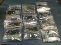
just finished packing the kits, only keratherm cutting to go, i'm sending an email out tonight regarding the alternate heatsinking as in my post above to get an idea of who would be keen so I can finalize the size I cut, finish that this week and get everything on the way.
I might grab 10 Ed, we'll see when you do it, pretty non-plussed indeed. thanks DK..... mouser were nearly 3x that when I last bought one there a month ago, 11AUD nearly I think
actually no, probably about even (still under, i'm not going to do the math to find out by how much so I can be pissed) because shipping was free as came straight here. there was bugger all price break for bulk for ours too. I wonder why, perhaps the new Ti based stock is cheaper because larger volumes were produced?
Attachments

Last edited:
- Status
- Not open for further replies.
- Home
- Group Buys
- The Wire LPUHP 16W Power Amp parts GB