haha just rechecked the datasheet, wow no wonder these things have proven so indestructible. operating temp of constant 85c max junction temp of 150c internally current limited. the buffers I'm pretty sure will actually cool down unless driving a really low Z load to the max. still think the angle top and bottom is the best and cheapest heatsink
You don't have to tell me about why heatsinking the tops of the buffers won't do much, I know that. I'm just wondering how much the thermal junction temperatures would be affected by cooling the bottom and why the bottom is getting that much hotter than the top, since FR4 has a fairly low thermal conductivity.
Anyways, am I not allowed to have some scientific curiosity without being fleeced by you qusp? Sheesh, I'm not even asking if there are boards available! 😛
Anyways, am I not allowed to have some scientific curiosity without being fleeced by you qusp? Sheesh, I'm not even asking if there are boards available! 😛
Last edited:
You don't have to tell me about why heatsinking the tops of the buffers won't do much, I know that. I'm just wondering how much the thermal junction temperatures would be affected by cooling the bottom and why the bottom is getting that much hotter than the top, since FR4 has a fairly low thermal conductivity.
Anyways, am I not allowed to have some scientific curiosity without being fleeced by you qusp? Sheesh, I'm not even asking if there are boards available! 😛
not at 9am after no sleep you arent
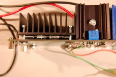
 lol its all good. well for starters the lme49990 are there and as ive said these things are the hottest things on the board (albeit with much lower mass). its on the underside, so air convection is probably doing bugger all, its possible if I turned the amp upside down the 'top' side (now underneath) would be hottest. its also possible that the radiated heat through the copper, through the epoxy is still more direct than radiating outwards + the impedance of the epoxy as its a shorter distance through the material to my finger if i'm touching directly underneath. I cant touch near the die of the buffers on the top of the board, bas thats where the body is and its considerably thicker. I didnt touch the actual tab of the buffers, perhaps I should try that hehe 😱 but I can touch directly under the buffer die/tab under the board and apart from touching the lme49990 itself, this area of copper is the hottest part.
btw I was more replying to everyone about the buffer bodies not just you, because in the other thread bcg27 asked if we would be ok just using the bom heatsink and since unaided its only touching the bodies its not going to be very effective IMO given the info I have at hand at the moment. opc may be able to enlighten us wrt how it behaves loaded.
it may be totally irreverent as the parts can handle it even if its a bit disconcerting and the reservoir caps are on a different section of copper and the difference in temp is dramatic, the PSU section is barely warm, so other than through case temp they should be fine also
Last edited:
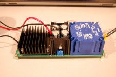
Here is my standard implementation of the LPHP amplifier. Everything is built according to the original specifications with the standard parts. I've been using it for almost two weeks and I haven't had any overheating issues. I am using a generic inexpensive thermal interface material. When idling the heat sink temperature stabilizes at 34 degrees Celsius, the bottom side of the PCB idles at 35 degrees. The opamp temperature stays at 48 degrees. At full blast the heat sink warms up to 44 degrees. The power supplies are set to 17.95V.
Turning the amps ON was easy. I set the voltages and everything just worked. I forgot to mention that I triple-checked all circuits for shortcuts, the polarity of the capacitors and the diodes, and the isolation of the heat sinks.
The sound quality is world-class! I played the amps at full blast on a pair of B&W CM1 and I couldn't notice any imperfection. And yes, I've noticed clearly pronounced details and recording defects that I haven't heard before.
Attachments
The sound quality is world-class! I played the amps at full blast on a pair of B&W CM1 and I couldn't notice any imperfection. And yes, I've noticed clearly pronounced details and recording defects that I haven't heard before.
Quite interesting, CM1 is 84dB sensitivity and 8ohm nom (5ohm min). I use a pair for rear speakers. I was wondering about how these would go with CM5 88db, 8ohm (3.5ohm min <- this might be a worry, I can't find any data on what freq this min happens at though 😡). Perhaps they'll go a bit better than I thought and I can put my active speaker adventures on hold for a while until I can fund it in a more over the top fashion 😎
By the look you're using SE input, what gain are you using? 21dB?
Also good to know that the opamp temps don't appear to be effected by the buffer temps pushing more heat into the PCB.
Here is my standard implementation of the LPHP amplifier. Everything is built according to the original specifications with the standard parts. I've been using it for almost two weeks and I haven't had any overheating issues. I am using a generic inexpensive thermal interface material. When idling the heat sink temperature stabilizes at 34 degrees Celsius, the bottom side of the PCB idles at 35 degrees. The opamp temperature stays at 48 degrees. At full blast the heat sink warms up to 44 degrees. The power supplies are set to 17.95V.
Turning the amps ON was easy. I set the voltages and everything just worked. I forgot to mention that I triple-checked all circuits for shortcuts, the polarity of the capacitors and the diodes, and the isolation of the heat sinks.
The sound quality is world-class! I played the amps at full blast on a pair of B&W CM1 and I couldn't notice any imperfection. And yes, I've noticed clearly pronounced details and recording defects that I haven't heard before.
ok, well it seems even just having A heatsink is enough,...heatsink...drool.
seems illogical that having contact with something that is barely warm could drop it that much when the rest of the board (the amp section at least) is considerably hotter. I dont think i'm overestimating with my 50-55c temps, it did seem to cool somewhat after being on for a while longer than 10 minutes up till 10 mins the lme49990 were only 5 just second touch material and opc has confirmed that they get quite hot at 18v, perhaps combined with not having any heatsink at all for the buffers the combined temp is higher.
well thats reassuring; thanks Exa065
theres definitely no problem with the build, no shorts, no signs of oscillation in the output
I am using SE 15 dB gain - just enough for use with the output stages of my DAC. The B&W CM1s are used just for testing. The proper implementation would be to use crossovers before the amplifiers. I hesitate to open the B&Ws. They are so good and so well balanced - no room is left for improvements.By the look you're using SE input, what gain are you using? 21dB?.
heres some tips I emailed to hochopeper just copied, so nvm the name references
the way this amp is designed makes it a breeze to test before switching on. this is after building up the PSU and testing and setting Vout before moving on with the amp build. I found that with these sumR trannies the vout I set unloaded dropped only a matter of 3mv under idle conditions with the amp fully finished bar heatsink.
so to test for shorts to ground and pin to pin for the whole amp; because the buffers are all in parallel
well of course your opamp is cooler, theres only one on its own, I think we'll find that given how close together they are having 3 will add a few degrees minimum. still sounds like its all covered, but I do think my estimates of temps are about right, just that the heatsink is more effective than it would seem
the way this amp is designed makes it a breeze to test before switching on. this is after building up the PSU and testing and setting Vout before moving on with the amp build. I found that with these sumR trannies the vout I set unloaded dropped only a matter of 3mv under idle conditions with the amp fully finished bar heatsink.
so to test for shorts to ground and pin to pin for the whole amp; because the buffers are all in parallel
the above also covers testing each rail to ground and the output to ground as a matter of courseon one buffer test tab to pin 1 and 3 (these are all connected to neg rail), then tab, pin 1 or 3 to pin 2, 4, 5 then pin 4 to 5 and you have all of the buffers ohmed out. can test from ground to 1, 3 or tab, 4,5 if you like, but it would be a pretty heroic effort to short the buffer to ground somehow you can test the lme49990 too if you like, but you should have soldering an soic8 down by now yeah? ha
really fun little build and looks great. I have a neat little mounting trick for the regs that looks great and should be done. use an allen screw with flush mounting washer with the head on the OUTSIDE of the heatsink and an isolation washer, then lock washer, then m3 nut on the INSIDE, looks excellent, spreads the heat better and also allows servicing, having the head of the screw on the inside would be a total pita to undo as its so obstructed
well of course your opamp is cooler, theres only one on its own, I think we'll find that given how close together they are having 3 will add a few degrees minimum. still sounds like its all covered, but I do think my estimates of temps are about right, just that the heatsink is more effective than it would seem
Last edited:
Those of us with warmer ambient temps probably just need to make sure the enclosure is reasonably ventilated I guess. That's probably a good idea anyway...
Exa, I agree there isn't a lot wrong with the B&W CM series speakers (perhaps if you're a bass nut these standmounts aren't for you without some sub) but well diy is addictive and I'd like to try my hand at an active version of a zaph ZD5 if I ever was to grow tired of these. Maybe with 3 different high performance amps to chose from I will just stop and listen for a while?
Exa, I agree there isn't a lot wrong with the B&W CM series speakers (perhaps if you're a bass nut these standmounts aren't for you without some sub
Last edited:
Exa065, thanks for the numbers, any chance of one more? you say at full blast the heatsink is 44 degrees, given that the buffers where they contact the heatsink are at least 10-15c lower than the pcb, by my reckoning that would make the pcb and lme49990 60-65c. can you please tell me what the pcb and opamp temp is at full blast?
Those of us with warmer ambient temps probably just need to make sure the enclosure is reasonably ventilated I guess. That's probably a good idea anyway...
my temps are uncased on an open bench in the beginning of winter, how do I make the inside of a case in summer better than that? no i'm just going to either try and forget I know what the temps are given the opamps are pretty hardy and its pretty localized, or go with the copper or Al angle bracket top and bottom bolted through
I was going to try running without heatsinks for a while till I figured out what I was doing for chassis now that needs an entire rethink and refinance =(, but i'm not feeling good about that anymore
Last edited:
You don't try to beat it in summer, I guess I was more suggesting that without good ventilation then these localised temps will give a bigger risk of heat soak/thermal runaway which will kill the deltaT comparison that we're making to extrapolate to higher ambient temp.
I suppose its possible to do the angle bracket as well as the bom heatsink or something similar ...
We've really got to stop calling this weather winter hey, there's Canadian's roaming these forums, what will they think if they look up our forecast?
I suppose its possible to do the angle bracket as well as the bom heatsink or something similar ...
We've really got to stop calling this weather winter hey, there's Canadian's roaming these forums, what will they think if they look up our forecast?
well yeah sure, but it IS the beginning of our winter and I did specify 15c ambient, so that makes the opamps by my estimate and withouit any heatsink at all; a 35-40c rise above ambient. given average ambient in QLD summer and...
so the opamps are definitely getting little copper hats
just a little bit annoying i'm having to run through all of this again.... of course we dont know what is the reason for that; it could be a very good one, but yeah who knows...
so the opamps are definitely getting little copper hats
just a little bit annoying i'm having to run through all of this again.... of course we dont know what is the reason for that; it could be a very good one, but yeah who knows...
Last edited:
Those are some awesome build pics guys! I'm really happy to see these starting to come to life.
qusp:
Great job on the build! I do think you're worrying a little too much about the heatsinking, but I know how particular you are, so hopefully we can find a solution that works well for you.
If you want a good canned solution, I would strongly suggest buying two of the BOM heatsinks per amp, and bolting one on the top and one on the bottom using TIM to isolate the bottom one from the PCB and thermal grease or a good TIM on the top. It's certainly not ideal in terms of heat transfer, but keep in mind that the amp is essentially fine with nothing, so adding even little bits goes a long way. A setup like that would probably only run about 10C above ambient even under moderate load.
As for the op-amps, just use the common copper RAM sinks with the adhesive backs. One should cover all three front end op-amps.
exa065:
That is a seriously stunning build. Incredibly clean, great mounting setup for the heatsink, and a beautiful job on the soldering. I wish mine looked that good!
I also really appreciate your feedback on the sound and the temps. I'm glad there's at least one other person who has had the chance to hear it 🙂
I'm also glad to hear it paired well with the B&W CM-1. I've been primarily listening to these with very high efficiency speakers, so it's good to hear they can hold their own when the going is a little tougher.
Regards,
Owen
I can relate to qusp's concern about temps. If he's seeing ~40deg temp rise on the opamps and we can easily get ambient temps into high 30s we're then nudging the max operating temp without considering impact of having it all mounted inside an enclosure stacked amongst a bunch of other gear all trying to dump a bunch of heat as well. This is a worst case and I'll have my aircon on long before then, some people don't like aircon though so actually have realistic chance of seeing this worst case.
We probably didn't consider opamp temps at all initially and focused on the buffers which seem less of an issue now.
I'm trying to find a way to calculate how much we reduce the temperature by putting heatsink on the opamp. I know this is kind of academic and lowering it a bit will probably give us all that we need. But I just like working these things out beforehand. Can someone check my logic in calc below?
SOIC8 opamp package Thermal resistance = 145°C/W
deltaT ~ 40°C (rise above ambient based on qusp temp estimation with 18V rails)
So are we really talking about total dissipation of roughly:
1 / (145/40) ~ 1/3W
Obviously this isn't all going to the top of the opamp case but I guess its probably most of the heat coming through the top since that's the main surface area to free air ...
Say we get something like one of these - MC14 BGA Memory Heatsinks - Rouchon Industries Inc., dba Swiftech - PC Liquid Cooling Systems CPU Cooler VGA Water Block Heatsink Pump Radiator Heat Exchanger Kit - for each opamp then we'll likely see heatsink temps of 2 or 3°C above ambient max assuming that maybe only 2/3 of the 1/3W of heat will actually go directly into the heatsink.
Based on that rough guess of 2/3 the heat total going through the heatsink then remainder still dissipated through case we are back to
(1/3)*(1/3)=1/9W * 145°C/W = 16°C rise from the heat through the case
So all up roughly 19-20°C (rise from heat through heatsink + rise from heat through opamp case) above ambient. Which with say 50°C temps inside an enclosure still gets pretty toasty, but 15°C below the 85°C limit on the datasheet. Someone tell me I haven't made an incorrect assumption somewhere in that?
Alternatively we could just use lower the rail voltages ...
Last edited:
it would probably be polite to ask if opc minded, given hes making this into a commercial product
The design is opc's to make pcbs and finished amplifiers with as he choses, he has made pcbs and those of us who were able to get in on the first round of pcbs that he offered have them now.
He has, in this thread, indicated that finished complete amplifiers based on the design in this thread are something that he is going to make into a commercial product.
For someone else to copy this design and create the same would be seen less favourably.
He has, in this thread, indicated that finished complete amplifiers based on the design in this thread are something that he is going to make into a commercial product.
For someone else to copy this design and create the same would be seen less favourably.
- Home
- Amplifiers
- Solid State
- The Wire - Low Power Ultra High Perfromance (LPUHP) 16W Power Amplifier