"The Wire AMP" Class A/AB Power Amplifier based on the LME49830 with Lateral Mosfets
A new run of these boards is now available! Please see the following thread for details:
http://www.diyaudio.com/forums/soli...ble-here-bal-bal-se-se-lpuhp.html#post3516741
Hi Guys,
There's a new addition to "The Wire" series of projects I've been working on lately.
It's push-pull amplifier based on the LME49830 front end which drives a pair of ACD101NDD and ACD103PDD lateral mosfets. It's immensely versatile in that you can run essentially any rail voltage from about +/- 10V up to about +/-90V on the mosfets and get anywhere from 1W to 400W of output depending on the load and the rails. This is an amp that can be tailored to any situation.
You can also run the amp in class A, class AB, or class B if that's your thing.
For the input, you can run either fully balance, or with just one 0R jumper it can be configured for SE input. You can run the amplifier AC or DC coupled. There are separate supply options for running the LME49830 on higher rails than the mosfets which improves efficiency and allows for a good regulated supply for the front end. Alternatively, with a pair of 0R jumpers, you can run just a single +/- supply for both the LME and the mosfets.
The board is small enough to fit pretty much anywhere, and all you need to provide is the power supply and the heatsink! I've even got an optional regulated supply board for the LME section.
I've attached the schematic, the Excel worksheet to calculate power outputs and rails, along with the layout and a BOM.
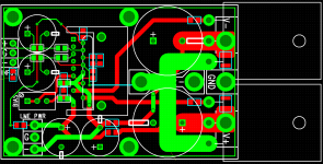
The PCB will be a 3 layer design with a ground plane in the middle and signal routing on either side. The LME has its own heatsink and the two mosfets are mounted on a user supplied sink off the end of the board. The board measures 2.45" by 1.6" and has all the required mounting points.
I will also be running a kit with this that includes all of the parts required to build a complete amplifier. All the user will need to supply is the main heatsink and the power supply.
PCB's are going to be $12 per channel, and a full kit including all 0.1% thin film resistors, and the best caps available for this application will be $78 per channel. I've attached the price list for the amplifier kit which contains all the details.
There will be 50 boards made available, and it will be first come first serve. Please post here if you're interested in a just a board, or a board and a kit, along with how many of each. Any technical question are welcome as well!
Measurements to follow!
EDIT - 27/05/2012
The schematic and layout below are incorrect. For the updated information, along with the assembly guide, please see this post:
http://www.diyaudio.com/forums/soli...-lme49830-lateral-mosfets-75.html#post2920157
Cheers,
Owen
A new run of these boards is now available! Please see the following thread for details:
http://www.diyaudio.com/forums/soli...ble-here-bal-bal-se-se-lpuhp.html#post3516741
Hi Guys,
There's a new addition to "The Wire" series of projects I've been working on lately.
It's push-pull amplifier based on the LME49830 front end which drives a pair of ACD101NDD and ACD103PDD lateral mosfets. It's immensely versatile in that you can run essentially any rail voltage from about +/- 10V up to about +/-90V on the mosfets and get anywhere from 1W to 400W of output depending on the load and the rails. This is an amp that can be tailored to any situation.
You can also run the amp in class A, class AB, or class B if that's your thing.
For the input, you can run either fully balance, or with just one 0R jumper it can be configured for SE input. You can run the amplifier AC or DC coupled. There are separate supply options for running the LME49830 on higher rails than the mosfets which improves efficiency and allows for a good regulated supply for the front end. Alternatively, with a pair of 0R jumpers, you can run just a single +/- supply for both the LME and the mosfets.
The board is small enough to fit pretty much anywhere, and all you need to provide is the power supply and the heatsink! I've even got an optional regulated supply board for the LME section.
I've attached the schematic, the Excel worksheet to calculate power outputs and rails, along with the layout and a BOM.
The PCB will be a 3 layer design with a ground plane in the middle and signal routing on either side. The LME has its own heatsink and the two mosfets are mounted on a user supplied sink off the end of the board. The board measures 2.45" by 1.6" and has all the required mounting points.
I will also be running a kit with this that includes all of the parts required to build a complete amplifier. All the user will need to supply is the main heatsink and the power supply.
PCB's are going to be $12 per channel, and a full kit including all 0.1% thin film resistors, and the best caps available for this application will be $78 per channel. I've attached the price list for the amplifier kit which contains all the details.
There will be 50 boards made available, and it will be first come first serve. Please post here if you're interested in a just a board, or a board and a kit, along with how many of each. Any technical question are welcome as well!
Measurements to follow!
EDIT - 27/05/2012
The schematic and layout below are incorrect. For the updated information, along with the assembly guide, please see this post:
http://www.diyaudio.com/forums/soli...-lme49830-lateral-mosfets-75.html#post2920157
Cheers,
Owen
Attachments
Last edited:
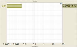
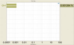
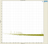
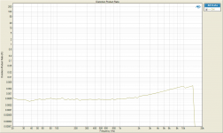
Attached below are the measurements for the prototype that this project is based upon.
I ran a worst case test setup with +/- 40V rails on both the LME and the mosfets. The supply was unregulated and sat at a nominal 42VDC under only the load of the bias. The bias was set to 360mA which meant the channel was dissipating about 30 watts at idle. This is considered a class AB setup.
A more ideal setup would be to provide the front end with a regulated supply voltage that is about 10V higher than the rails used for the mosfets. This allows the output stage to be driven fully rail to rail which means more power output with less dissipation, which gives higher efficiency.
The regulated front end would also drastically reduce the 60Hz noise (along with all the harmonics) that can be seen in some of the measurements.
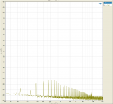
Overall, these numbers are superb and would absolutely destroy any of the class D designs I've seen so many people here get excited about. The noise floor is exceedingly low, and distortion performance is some of the lowest I've ever measured in a power amplifier. At 2.5W with standard class AB bias, you're looking at about 0.000814% THD+N.
Cheers,
Owen
I ran a worst case test setup with +/- 40V rails on both the LME and the mosfets. The supply was unregulated and sat at a nominal 42VDC under only the load of the bias. The bias was set to 360mA which meant the channel was dissipating about 30 watts at idle. This is considered a class AB setup.
A more ideal setup would be to provide the front end with a regulated supply voltage that is about 10V higher than the rails used for the mosfets. This allows the output stage to be driven fully rail to rail which means more power output with less dissipation, which gives higher efficiency.
The regulated front end would also drastically reduce the 60Hz noise (along with all the harmonics) that can be seen in some of the measurements.
Overall, these numbers are superb and would absolutely destroy any of the class D designs I've seen so many people here get excited about. The noise floor is exceedingly low, and distortion performance is some of the lowest I've ever measured in a power amplifier. At 2.5W with standard class AB bias, you're looking at about 0.000814% THD+N.
Cheers,
Owen
Attachments
-
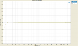 Frequency Response.png69.7 KB · Views: 21,166
 -
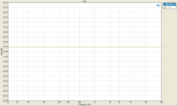 Gain balanced.png60.4 KB · Views: 20,172
 -
 THD+N Ratio balanced input 2.5W.png57.7 KB · Views: 19,774
 -
 Amp Noise Floor BAL.png94.5 KB · Views: 2,075
 -
 THD+N Ratio 100W.png59.1 KB · Views: 1,559
 -
 THD+N Ratio SE input 2.5W.png57.4 KB · Views: 19,289
 -
 Amp Noise Floor SE.png103.2 KB · Views: 2,099
 -
 Distortion Product Ratio vs freq 180mV input.png56.6 KB · Views: 1,811
 -
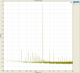 FFT Spectrum Monitor balanced input 2.5W.png95.7 KB · Views: 2,148
 -
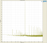 FFT Spectrum Monitor 112W.png99.5 KB · Views: 2,406
Hi Owen,
I like it! Just got myself a pair of PSB Alpha B1 bookshelf speakers and was looking to build a nice amp for them. Count me in for 2 full kits (PCB + parts) as well as 2 PCB-only.
Thanks!
I like it! Just got myself a pair of PSB Alpha B1 bookshelf speakers and was looking to build a nice amp for them. Count me in for 2 full kits (PCB + parts) as well as 2 PCB-only.
Thanks!
yeah definitely 4 not 2 for me, so can we make this a bit more organized guys? i tried to start it just up there but noone followed suit.
qusp 4 x PCB only
L-Train 2 x parts kit and 4 x PCB
Ferrari 4 x PCB only
holminator 2 x pcb and 2 x parts kit
1543 7 x PCB only
____________________
21 x pcbs
4 x parts kits
ive counted the pcbs in the kits, easier to keep them separate, so perhaps when you make the post, list the pcb and part separately, so if you want a full kit with parts, list as
1 x pcb
1 x parts kit
does that make sense opc? guys?
That's spot-on! Follow that method and it'll make my life much easier.
I'll compile the usual list once there are a few more people listed.
Cheers,
Owen
I'll compile the usual list once there are a few more people listed.
Cheers,
Owen
Hi Owen,
Put me down for 2 boards. I know I'll be kicking myself if I don't jump on the opportunity now.
MrSlim 2 pcb
thanks
Put me down for 2 boards. I know I'll be kicking myself if I don't jump on the opportunity now.
MrSlim 2 pcb
thanks
What's with all the interesting projects lately?
I'm broke!
and of course I am in for:
CafeNoir 4x pcb and 2x parts kits
thanks
I'm broke!
and of course I am in for:
CafeNoir 4x pcb and 2x parts kits
thanks
I would love to try out it someday, so 2 boards!
I really like these LME chips, I think I have already one sample
I really like these LME chips, I think I have already one sample
Is anyone concerned about how close the Mosfets are spaced? Looks like you will have a serious problem with thermal crowding with your heat sinking.
qusp 4 x PCB only
L-Train 2 x parts kit and 4 x PCB
Ferrari 4 x PCB only
holminator 2 x pcb and 2 x parts kit
1543 7 x PCB only
mr Slim 2 x pcb only
Cafe Noir 4 x pcb and 2 x parts kits
dillmeister 2 x pcb only
Spacehead 2 x pcb only
multisync 4 x pcb only
____________________
35 x pcbs
6 x parts kits
ive counted the pcbs in the kits, easier to keep them separate, so perhaps when you make the post, list the pcb and part separately, so if you want a full kit with parts, list as
1 x pcb
1 x parts kit
hahaha seriously guys, did anyone read what i wrote and then opc confirmed it would make his life easier?
I tried mate, i'm going to collate the ignorers orders one more time hehe, probably they just didnt see it because your post took us over the next page
@ JLH, no not really worried, if people are worried they can just wire them in
L-Train 2 x parts kit and 4 x PCB
Ferrari 4 x PCB only
holminator 2 x pcb and 2 x parts kit
1543 7 x PCB only
mr Slim 2 x pcb only
Cafe Noir 4 x pcb and 2 x parts kits
dillmeister 2 x pcb only
Spacehead 2 x pcb only
multisync 4 x pcb only
____________________
35 x pcbs
6 x parts kits
ive counted the pcbs in the kits, easier to keep them separate, so perhaps when you make the post, list the pcb and part separately, so if you want a full kit with parts, list as
1 x pcb
1 x parts kit
hahaha seriously guys, did anyone read what i wrote and then opc confirmed it would make his life easier?
That's spot-on! Follow that method and it'll make my life much easier.
I'll compile the usual list once there are a few more people listed.
Cheers,
Owen
I tried mate, i'm going to collate the ignorers orders one more time hehe, probably they just didnt see it because your post took us over the next page
@ JLH, no not really worried, if people are worried they can just wire them in
Last edited:
Hi JLH,
At these power levels I'm not overly concerned about it. They are closer than I would have liked, but hanging them off opposite sides of the board resulted in very poor routing.
An easy trick would be to bend the leads so that both devices are spread a little farther apart, or alternatively just mount the devices where you need them and run the proper wire leads to each pin (large wires required for D-S).
As long as the heatsink has a reasonable thickness, having the devices 1" apart or 0.1" apart makes very little difference overall. The limiting values will be the thermal resistance between the package and the sink, as well as the thermal resistance to the extremes of the heatsink. In reality, you'd have to get the devices several inches apart to really improve the situation.
Does anyone know of a good thermal simulator that would help model this?
Regards,
Owen
- Home
- Amplifiers
- Solid State
- "The Wire AMP" Class A/AB Power Amplifier based on the LME49830 with Lateral Mosfets