Peter Daniel said:I favour are 15n X7R 0612 and 330n X7R 0612 from DK.
Please give me some more information about these very useful caps (web address, part number, full brand name or place you buy from would be very useful)
Petter
I try to like it Peter but I am stuck in a pcb's-look-better period at the moment ( as always 😉 ). Never liked hardwiring and I probably won't ever like it except for prototyping. Ever returning thing is the long time from schematic to board. Hard to admit but I see the PCB as an esthetic feature although it shouldn't be IMO. Also I have a firm belief that pcb's are more reliable as regular experiments with hardwiring reveiled.
Regarding the bypassing of caps. Were the BG's you bypassed burnt in ? I bypassed with 220 nF X7R ( Kemet ) and I wasn't impressed.
Regarding the bypassing of caps. Were the BG's you bypassed burnt in ? I bypassed with 220 nF X7R ( Kemet ) and I wasn't impressed.
Yes, they were burned in for at least a month of constant use. I took them from the other DAC.
Digikey.com part#:
PCC2173CT
PCC2185CT
Regarding PCB vs. p2p, I agree that pcb provides more convenience and better look and I don't think that wiring p2p has such tremendous advantage as some people try to portray.
But I also believe that going into 3D layout has its advantages and in many cases simplifies connection and make them much shorter (and actually "looking better"). That's why I will continue using combination of PCBs and 3D layout.
My thanks to Jonathan Carr for inspiration 😉
PS: Especially in case of CS8412 and TDA1543 connecting I2S lines is not that simply and placing the DAC on top of receiver makes things much easier. And the length of that lines is important, I presume. Same goes for shared and compact ground plane.
PS: Especially in case of CS8412 and TDA1543 connecting I2S lines is not that simply and placing the DAC on top of receiver makes things much easier. And the length of that lines is important, I presume. Same goes for shared and compact ground plane.
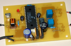
Sorry, no groundplane. Some parts are under the board in case you think it is underpopulated. This was my very first prototype PCB of a TDA1543 DAC as discussed on the Amp board. I2S lines are very short. I am 15 versions further ( not all actually built ! ) in time but still not totally satisfied with the final version. That one features some 3D as well ( you'll need the special 3D glasses however 😉 ).
Attachments
Peter Daniel said:Here's what Jonathan Carr says about them[/url]
There are different kinds of silver mica.
The red-brown ones that come in drop form "dipped" are mostly magnetic
 and tolerance is 5%.
Some german brand is not magnetic and 1% or even 0,5%.
I have a huge collection but did not compare them to other stuff yet. So many things to do...
 I recently observed one well known former member of this forum buying a pair on ebay for a high price.
 I'm well aware of german siver mica brands. Dice45 favoured them as well (and I trust his judgement) and he even mentioned that some of those caps have leads riveted for better contact😉
jean-paul said:
I am 15 versions further ( not all actually built ! ) in time but still not totally satisfied with the final version.
What's the main concern here to achieve total satisfaction? Maybe I could help?😉
Are you still using only 2 regualtors and shared raw supply? I wouldn't be surprised you are not happy😉
Hi Peter
Nice job with the dac, I'm currently using a modified Alpha5+ (TDA1541A S2,Multicap RTX coupling caps etc) I'm very pleased with the sound but would be interested in trying the TDA1543 as well.
I have an unused what looks like a standard TDA1543 chip in my spares box along with some 100uf BG N caps etc so I'll give it a try. The only thing I don't have is the CS8412 and those regs you use
Kind Regards
Ron
1000R
What a lovely build, as usual for Peter!
You might try 1000R i/v resistors, found to be nicer by the "attack of the clones" tda1543 project.
What a lovely build, as usual for Peter!
You might try 1000R i/v resistors, found to be nicer by the "attack of the clones" tda1543 project.
I guess resistors values depend on supply voltage as well. I've built 5V DAC with all 3 resistors being 1000R, but I prefer the sound of this one with 8V supply and 3K for I/V resistors. The DAC seems to be more dynamic and 3 dimentional.
The regulators are Panasonic AN8005 and AN8008 (available from DigiKey). I noticed Kusunoki used them so I decided to give them a try. I compared those against LM7808 and AN parts sound better (to me).
100u BG is good for DAC bypass, but it's not really desirable for other chips. I wouldn't go higher than 10u on receiver bypass.
Peter, why do you still use a reciever chip? Since all (I think) your transports are philips or marantz, wouldn't it be better to use I2S directly?
Because this is a prototype for an outboard DAC. I truly didn't noticed that much degradation when cable connection to the DAC is made. I guess it is very much dependant on implementation, but my all in one box unit doesn't sound better than separates.
I have a transport in the making and it will feature integrated DAC, but having DAC separate has it's advantages too (especially when you do tweaking).
I have a transport in the making and it will feature integrated DAC, but having DAC separate has it's advantages too (especially when you do tweaking).
Just a quickie..
Doesn't that 1543 run rather hot with an 8v supply?
Just peeking at the data sheet ,I note a max dissipation of
250mw...
I do not recollect seeing any measures being taken to
keep single chips cool.
[ well, other than the dead bug on a ground-plane approach ..hehe]
 ..Seems like a cue for one of my excessive heatsinks!😉
But I do worry though...
Cheers
Setmenu
Doesn't that 1543 run rather hot with an 8v supply?
Just peeking at the data sheet ,I note a max dissipation of
250mw...
I do not recollect seeing any measures being taken to
keep single chips cool.
[ well, other than the dead bug on a ground-plane approach ..hehe]
..Seems like a cue for one of my excessive heatsinks!😉 But I do worry though...
Cheers
Setmenu
I didn't notice any particular high temp of the DAC chip. It is also attached to the ground plane, which being made of copper foil, also takes some heat away.
Hi Peter
Interesting, I asked because originally I had intended to use
opamp iv conversion and 5v supply.
But now in the interests of compactness [got to cram the dac and an amp into as small an enclosure as possible] I wish to try the passive iv form.
I also get the impression the passive would sound better?
You mention 'compact shared ground planes'.
So obviously you have found no problems with the receiver/dac
sharing them..
I read so many conflicting viewpoints here..what's a noob to do..

Perhaps these circuits/implementations are not so sensitive to these things, as I see every thing from large planes to none!
On the subject of IV resistors, I see you are using 3k and 1.5k ref
values.
Could I just 'copy' [sorry..] this or would you advise implementing a pot to fine adjust [due to chip tolerance variation? ]?
I hope my questions are not too noobish , as I very much appreciate your input.
Thanks
Setmenu
Interesting, I asked because originally I had intended to use
opamp iv conversion and 5v supply.
But now in the interests of compactness [got to cram the dac and an amp into as small an enclosure as possible] I wish to try the passive iv form.
I also get the impression the passive would sound better?
You mention 'compact shared ground planes'.
So obviously you have found no problems with the receiver/dac
sharing them..
I read so many conflicting viewpoints here..what's a noob to do..
Perhaps these circuits/implementations are not so sensitive to these things, as I see every thing from large planes to none!
On the subject of IV resistors, I see you are using 3k and 1.5k ref
values.
Could I just 'copy' [sorry..] this or would you advise implementing a pot to fine adjust [due to chip tolerance variation? ]?
I hope my questions are not too noobish
, as I very much appreciate your input.Thanks
Setmenu
I indeed tend to believe that passive I/V sound better than active stage. I found the power supply for active stage to be very influencial on the sound and finding good solutions here wasn't that easy. The active stage always sounds less natural than properly chosen resistors.
It seems to be the opinion that passive I/V lacks dynamics, yet I didn't observe it. Especially, when circuit is powered by separate batteries (one for DAC, one for the receiver), the dynamics and bass drive are incredible.
I tried few different resistor types and found that Rikens sounded most naturaly (better than Caddocks and Vishays). The closest values that could be obtained were 2k7 and 1k5. They work well.
Hi Peter
I will not be using separate batteries, just a 9v nimh pack.
I wish I had the choice of 'exotic' resistors here in the UK.
I cannot find the likes of Riken etc here at all🙁
The only exotica I have located are some Tantalum variety at:
http://www.hificollective.co.uk/
?😕
Cheers
Setmenu
I will not be using separate batteries, just a 9v nimh pack.
I wish I had the choice of 'exotic' resistors here in the UK.
I cannot find the likes of Riken etc here at all🙁
The only exotica I have located are some Tantalum variety at:
http://www.hificollective.co.uk/
?😕
Cheers
Setmenu
I recollect reading somewhere that the cs8412 analogue and
digital supplies [when using dual regs] should have a pair of diodes connected in anti-parallel between them for protection?
I note seeing this implementation in some 'original' schematics.
I wondered what purpose this serves?
Cheers
Setmenu
digital supplies [when using dual regs] should have a pair of diodes connected in anti-parallel between them for protection?
I note seeing this implementation in some 'original' schematics.
I wondered what purpose this serves?
Cheers
Setmenu
It is to avoid "latch-up" at power-on. This occurs when one of the supplies is slower at power-on than the other. Chances are small that it happens but when fed with a transformer with separate windings chances are bigger. I had it once with a first version of a DAC ( chaos-wiring, some power transformers etc. ). The differences in power on leave the chip in an undefined state when it happens. In the case of CS8412 you'll notice that it won't lock.
With the older 78xx regulator series this "latch-up" happened quite often when a symmetric supply was realized with them. In older schematics of symmetric supplies with IC regulators you'll notice the diodes ( in reverse of course ! ) from output pins to ground to avoid "latch-up".
If you add the antiparallel diodes you'll never have the phenomenon, they don't add much to the total costs and they won't bring significant negative influences AFAIK. BTW it wouldn't surprise me if newer revisions of the CS8412 have those diodes already built in to avoid damage to the chip.
- Status
- Not open for further replies.
- Home
- Source & Line
- Digital Source
- The ultimate TDA1543 DAC layout??