Hi Forum
It has been over 6 years ago that I build my big 3 way speaker.
"building the best 3-way full range speaker"
Earlier this year we did a big renovation of the living room with attached kitchen and when this was done, I found the speakers a big too massive.
Maybe it is my age and the testosterone is diminishing but the speakers always were big.
So I am starting a new design, with 20% smaller footprint and 30% less volume.
Still a large speaker but a bit better suited to the room.
I will start a different thread on this built.
But..... I want to improve some parts on a design that will borrow a lot of the original as to my ears it is still a fantastic sounding speaker.
In the preparation to this new design I want to simulate better and measure more precise.
So, I bought an Earthworks M23R reference microphone.
This unit has an insane flat curve with a correction file that onlu has +/- 0.16dB of correction.
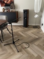
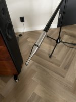
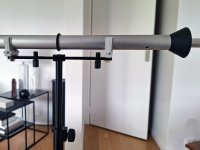
I designed a new mic stand by combining some parts of existing good available mic stand parts.
The reason not to go with a standard mic stand is the possible reflections the boom and mic-clamp can introduce.
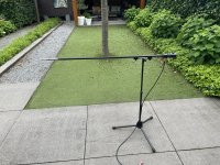
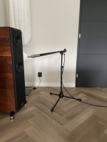
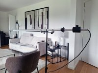
So the ideal speaker measurement setup is kind of a floating microphone with nothing close that can cause reflections,
The parts I used are:
It has been over 6 years ago that I build my big 3 way speaker.
"building the best 3-way full range speaker"
Earlier this year we did a big renovation of the living room with attached kitchen and when this was done, I found the speakers a big too massive.
Maybe it is my age and the testosterone is diminishing but the speakers always were big.
So I am starting a new design, with 20% smaller footprint and 30% less volume.
Still a large speaker but a bit better suited to the room.
I will start a different thread on this built.
But..... I want to improve some parts on a design that will borrow a lot of the original as to my ears it is still a fantastic sounding speaker.
In the preparation to this new design I want to simulate better and measure more precise.
So, I bought an Earthworks M23R reference microphone.
This unit has an insane flat curve with a correction file that onlu has +/- 0.16dB of correction.
I designed a new mic stand by combining some parts of existing good available mic stand parts.
The reason not to go with a standard mic stand is the possible reflections the boom and mic-clamp can introduce.
So the ideal speaker measurement setup is kind of a floating microphone with nothing close that can cause reflections,
The parts I used are:
- The main tube of a Gravity MS 23 XLR B Microphone Stand
- K&M 252 Black standard mic stand where the main tube is build out of 3 parts so the vertical pole can go pretty low
- An Adam Hall SDMSB 190 Stereo Bar that gets mounted on the K&M stand by standard 3/8” threaded bolt
- A K&M 21105 Counterweight (that I mount to the mic tube with a rubber door stopper)
- Some bolts, nuts, washers and 4 black electricity tube clamps.
Attachments

Last edited:

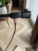
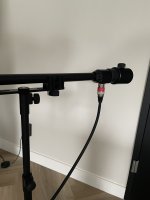
Very nice, could you show some details how you fix the counterweight to the Gravity mic tube please ?
Hi JCGA,
This was a bit of a fiddle as the M20 thread on the gravity tube was different then what I could get in a hardware store.
So I took an M10 hex bolt that I made thicker with tape and pushed that in the hole of the M20 end of the tube.
I also had a rubber doorstop that mounted snug over the M20 thread and that was in the end a nice enough construction to mount the counter weight dat I could fasten over the hex bolt head
Hope this makes sense (I rather leave all in place now it is still snug)
Or make a -preferably turnable in 5 degree steps- jig that allows at least 2 metres distance for the nearest floor/ceiling or wall.
Thank you PSchutThis was a bit of a fiddle as the M20 thread on the gravity tube was different then what I could get in a hardware store...
Did you get the correction data below 800Hz? The graph doesn’t show them.So, I bought an Earthworks M23R reference microphone.
This unit has an insane flat curve with a correction file that onlu has +/- 0.16dB of correction.
Not too difficult with a pressure transducer like a mike. You are above the internal vent frequency and below any acoustic resonances. That range can be tested with a coupler or a pistonphone ( not to 800 Hz) The problems start around 4 KHz with a 1/4" capsule. It gets complicated from 4K up and above 70 KHz the filter in the front limits the performance. Below is the spec for the B&K 4135 1/4". The solid line is no grid, the dotted one is with grid. The grid limits performance to 40 KHz.

Last edited by a moderator:
1audio -
I agree that many good measurement mics exhibit performance sufficient for their intended tasks. But even your graph shows deviations > 1 dB over a far more restricted frequency span vs the preposterous .01dB over 10-768 kHz range claimed by PSchut.
I agree that many good measurement mics exhibit performance sufficient for their intended tasks. But even your graph shows deviations > 1 dB over a far more restricted frequency span vs the preposterous .01dB over 10-768 kHz range claimed by PSchut.
For what its worth here is a recent cal file for my 4135. The low frequency range is pretty flat. At 20+ KHz there are some fluctuations but for humans they are academic. The cal on this mike has not changed in 35 years. I will be using it to benchmark my calibration capabilities.

Last edited by a moderator:
THIS!Or make a -preferably turnable in 5 degree steps- jig that allows at least 2 metres distance for the nearest floor/ceiling or wall.
The dispersion data will provide a LOT more information about the sound quality of your speaker than any on-axis SPL curve, no matter how accurate or precise the measurements is.
The dispersion data is one of the factors that make a good loudspeaker but is a result of several factors like selected units and enclosure design and cannot be really influenced anymore when the speaker is done. The on axis frequency response can.
So I would do my ultimate best to design a good enclosure, use the best drivers I can combine and then measure, listen and tweak the filter until I get the best result to my ears. The most accurate measurement will allow me to simulate the filter that will help me doing less trial and error soldering components, but the later is still needed.
And this all starts with a measurement setup described here.
It’s great that you removed the effects of early reflections from your microphone stand. This generally affects the top couple of octaves.
That is almost right. In the fine print Earthworks guarantee their M23R microphone to be within +/- 0.3dB between 10Hz and ~800Hz, Hence EW don't show/give frequency response chart or calibration file below ~800Hz. Also note that they provide compensation data using a substitution method (ie. substituting one microphone in place of another), so it is not as precise as the electrostatic actuator method. Despite that, it's more than sufficient to to take frequency response measurements.
However, I've found that for 2024 built EW M23, the second harmonic cannot be observed at lower than -60dB.
Reference:
https://www.diyaudio.com/community/...mnidirectional-microphones-for-diyers.412011/
You're probably thinking well, that's good enough for me, to which I won't argue with. But just be aware that whatever distortion you are measuring, you're probably measuring the whole signal chain, including your microphone preamplifier/capsule…
Reference:
https://www.diyaudio.com/community/...ement-microphones-actual-measurements.411218/
Yes, from 10Hz to 768Hz it is ruler flat within 0,01dB
That is almost right. In the fine print Earthworks guarantee their M23R microphone to be within +/- 0.3dB between 10Hz and ~800Hz, Hence EW don't show/give frequency response chart or calibration file below ~800Hz. Also note that they provide compensation data using a substitution method (ie. substituting one microphone in place of another), so it is not as precise as the electrostatic actuator method. Despite that, it's more than sufficient to to take frequency response measurements.
However, I've found that for 2024 built EW M23, the second harmonic cannot be observed at lower than -60dB.
Reference:
https://www.diyaudio.com/community/...mnidirectional-microphones-for-diyers.412011/
You're probably thinking well, that's good enough for me, to which I won't argue with. But just be aware that whatever distortion you are measuring, you're probably measuring the whole signal chain, including your microphone preamplifier/capsule…
Reference:
https://www.diyaudio.com/community/...ement-microphones-actual-measurements.411218/
Last edited:
Or make a -preferably turnable in 5 degree steps- jig that allows at least 2 metres distance for the nearest floor/ceiling or wall.
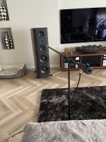
Nice MIC rig 🙂
Agree with @Boden.
Turntable (for measurements) is a must for proper simulation. I Will never return to random measuments on/off axis again.
- Home
- Design & Build
- Equipment & Tools
- The ultimate speaker measurement setup?