kilowattski said:Magura,
Are you using the attenuators you built from scratch?
That's the plan....the only excuse for making an 8 deck switch 😉
Magura 🙂
Henrik said:Hi Magura
It seems to me, that your fet pinlayout might be wrong.
Henrik
Hi Henrik
It also seems to me that my FET pinlayout is wrong 😉
Thanks again!!
Seems like I will have to make an ultra final layout🙄
Magura 🙂
Did you draw a schematic? Please post it if you did. It's a bit tough to follow your tracks😉
Steen🙂
BTW. I will save my 0,1uF Teflon caps for this one😀 😀
Steen🙂
BTW. I will save my 0,1uF Teflon caps for this one😀 😀
A schematic??? What's that???? 😎
I have to admit that I am too lazy to make a schematic when 90% is a copy of Kristian's version. I have basicly added bypass caps, gain adjustment and converted the 680R power 10W power resistors into 4*2K7 3W metal film.
Magura 🙂
I have to admit that I am too lazy to make a schematic when 90% is a copy of Kristian's version. I have basicly added bypass caps, gain adjustment and converted the 680R power 10W power resistors into 4*2K7 3W metal film.
Magura 🙂
steenoe said:
BTW. I will save my 0,1uF Teflon caps for this one😀 😀
Sounds like a good idea....
Magura🙂
That explains the IRF parts, turning the wrong way😀I am too lazy to make a schematic
Well, the circuit looks good to me as it is, maybe Henrik can find something to pick on 😀 😀
Very good idea, those 10Watters are hard to come by.4*2K7 3W metal film.
Edit again, arent those 680r's supposed to be 750r's?
Steen😎
steenoe said:
That explains the IRF parts, turning the wrong way😀
Steen😎
Nope, the explanation for that is unfortunately very simple. I simply remembered the pin layout being different, and felt no need to check the datasheet🙄
Magura🙂
I just saw this and realised it was not very elegantly putThat explains the IRF parts, turning the wrong way
 No offense, whatsoever
I am confident that this will turn out just great🙂
Steen.😎
steenoe said:I just saw this and realised it was not very elegantly put
I am confident that this will turn out just great🙂
Steen.😎
Feel free to have a laugh on me 🙂
It is usually a good sign when people can remember your mistakes.....that usually means that you don't make many.
No offense taken.
Magura 🙂
Hmmm, just studied yor layout a bit more!
The 0,22uF, is that a bypass for the output cap?`You saved a lot of space for that one! Wouldn't it be better to give room for one big MKP??
Steen.
Yep, that was the first time😀 😀
The 0,22uF, is that a bypass for the output cap?`You saved a lot of space for that one! Wouldn't it be better to give room for one big MKP??
Steen.
that usually means that you don't make many.
Yep, that was the first time😀 😀
Yes the 0.22uF is bypass for the output cap. AFAIK there is little point in putting an output cap bigger than 10uF in this circuit, but if I should turn out to be wrong about that, there is room for at least 20uF MKP.
The 0.22uF film/foil cap simply need that much space, and I sure like to have a film/foil cap for bypass for the output cap.
Magura 🙂
The 0.22uF film/foil cap simply need that much space, and I sure like to have a film/foil cap for bypass for the output cap.
Magura 🙂
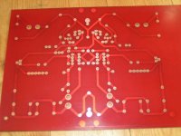
I just finished etching the first PCB this evening, PCB's of that size are sure a PITA, it's like all the problems grows with the size of the board.
The board is about A4 size (200mm*300mm).
http://www.briangt.com/gallery/album05
Magura 🙂
The board is about A4 size (200mm*300mm).
http://www.briangt.com/gallery/album05
Magura 🙂
Has anybody tested all BOSOZ preamps and compared what sounds the best.
Normal BOSOZ, with CSS and with X-ing.
What did your expirience show till now.
Greetings
Normal BOSOZ, with CSS and with X-ing.
What did your expirience show till now.
Greetings
promitheus said:Has anybody tested all BOSOZ preamps and compared what sounds the best.
Normal BOSOZ, with CSS and with X-ing.
What did your expirience show till now.
Greetings
I have build a few of them, but your question is too wide to give a reasonable answer. There are so many configurations of each type that you will find it hard to find a general answer.
Magura 🙂
What is the function of the two single diodes on the right??
I will include the zener mosfet protection, but find it hard to make a change to something I do not fully understand.
http://web.vip.hr/pcb-design.vip/xccs-pwr.gif
Cheers
Magura🙂
I will include the zener mosfet protection, but find it hard to make a change to something I do not fully understand.
http://web.vip.hr/pcb-design.vip/xccs-pwr.gif
Cheers
Magura🙂
... yes, and to protect the Hexfet (avoiding the reverse G-D voltage) when the power goes down.
Marcello
Marcello

- Status
- Not open for further replies.
- Home
- Amplifiers
- Pass Labs
- The ultimate CCS-X-BOSOZ