
GregGC said:hitsware, at another tread (http://www.diyaudio.com/forums/showthread.php?postid=260139#post260139)pointed out that OPA541/549 has jfet input (no worries for the Out DC offset), which I think makes it a very good candidate for the Ultimate/semi-Ultimate GC based on OPA541/549.
Greg
opa541 has jfet inputs. be aware that the opa chips should not be used with a gain higher than 26dB ideally not over 20dB because of the limited GBP.
my opa541 clone has dc-offset in the uV range 😉
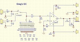
And this is my preferred setup that I listen to at home (it sound very good to me).
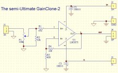
IMHO this should be the minimum number of parts if you want to have a bulletproof GC. The 1000uF caps have to be low ESR, Pana. FC type or other equivalents (in my case United Chemi-con LXY type).
Greg
IMHO this should be the minimum number of parts if you want to have a bulletproof GC. The 1000uF caps have to be low ESR, Pana. FC type or other equivalents (in my case United Chemi-con LXY type).
Greg
Attachments
Mad_K said:
opa541 has jfet inputs. be aware that the opa chips should not be used with a gain higher than 26dB ideally not over 20dB because of the limited GBP.
my opa541 clone has dc-offset in the uV range 😉
I have to build one one day based on the OPA541. It would be interesting to compare them.
miguel2 said:Greg,
What do you use for the diode bridges? And how many bridges? And snubbers?
Miguel
The bridges are nothing exotic. Regular 200V/40A bridge that you can mount on the chassie. I have separate power supplies for each channel and 2 bridges per channel. No snubbers. I haven't had the time (too busy listening to the GC) to try higher than 1000.0 PS caps, but considering the fact that I don't listen to very loud music I don't think I will here any difference. For output power below 25W/chanel 1000.0uF per rail per channel should be quite fine.
I am using one bridge of MUR860s for both channels, snubbered with 100nF. Have 12 more MUR860s waiting but I toooo lazy to put them in. It just sounds nice as it is.
Miguel
Miguel
miguel2 said:It just sounds nice as it is.
Miguel
Enjoy the music. Some times we forget that the reason for having the amp on the first place is the music we listen to.
Jfet input opamp and capacitor
Hi Greg,
Forgive my ignorance, do you mean that the DC-blocking capacitor is not needed for the Jfet input power op-amp in gainclone configuration? I am currently using OPA541s in non-inverting mode without the cap, and it sounds amazingly good.
Thanks for your kind input.
Best wishes,
Russell
GregGC said:hitsware, at another tread (http://www.diyaudio.com/forums/showthread.php?postid=260139#post260139)pointed out that OPA541/549 has jfet input (no worries for the Out DC offset), which I think makes it a very good candidate for the Ultimate/semi-Ultimate GC based on OPA541/549.
Greg
Hi Greg,
Forgive my ignorance, do you mean that the DC-blocking capacitor is not needed for the Jfet input power op-amp in gainclone configuration? I am currently using OPA541s in non-inverting mode without the cap, and it sounds amazingly good.
Thanks for your kind input.
Best wishes,
Russell
Re: Jfet input opamp and capacitor
The input cap is needed everytime you need to block a DC voltage comming from the source. That voltage would chnge the bias of the amp if applyed to the +in and it'll create output DC offset proportional to the DC gain of the amp. If you don't have a cap in ser. of the feedback resistor to GND (the ones that determined the gain of the amp, the 680/22k) than the DC gain of the amp is = to the AC gain (around 30 in this example). If you aply 0.01VDC to the +in you'll get 300mVDC offset at the output of the amp which would change the way the amp works (not in a good way). If there is a cap in ser of the 680 res. than the DC gain of the amp is 1, so the output DC voltage is the same as the input DC voltage (10mVDC is quite acceptable). In both case I don't take into account the offset input voltage which is the sam as if your source puts a DC voltage on the +in, but it's created by the amp itself (details in the books for opamps). So if the data sheet sais you that the amp can have upto 1mV offset and your amp has a DC gain of 30, you'd expect the worst case scenarion of 30mV DC offset at the output (quite OK). If You don't hav DC gain (cap in ser with 680) then the output will have max of 1mVDC offset. Mind you the cap in ser. of the 680 ohm res. also afetcs the sound quite a bit so the best case scenario is NO caps at all, if you can have a reasonable DC offset at the output of the amp.
From the data sheet, depending on the type OPA541 has a Voffset from 2-10mVDC or 0.1 to 1mVDC. The Offset currents are very small (JFET input) which allows you to not have to match the resistance to gnd that the +/- in see (that's what creates additional Voffset). So JFET is less sensitive to dif. in the resistance between -in/GND and +in/GND thus less DC offset at the output. In the case of GC and no input cap. the Volume pot changing the res. between +in/gnd every time you turn the pot. It goes from 0 to 50k for example. That's why it's good to have some kind of a resistor in ser of the +in (470 for example), so that the res +in/gnd never goes to 0 thus your Ibiass never create too big of a Voffset, thus less DC offset at the output.
So JFET would have an advantage in a way that the output DC offset wont change as much when changing the volume pot.
http://www.diyaudio.com/forums/showthread.php?postid=259680#post259680
After all that ranting (apologies for the long post):
If there is no DC Voltage present at the source (cd player or preamp...) output you'd be better off without the input and DC FB blocking cap because you'll have one/two less component for the signal to go through. So in your case you are fine (your output DC voltage is low enough (less that 30mVDC) I assume).
Greg
Russell Sit said:
Hi Greg,
Forgive my ignorance, do you mean that the DC-blocking capacitor is not needed for the Jfet input power op-amp in gainclone configuration? I am currently using OPA541s in non-inverting mode without the cap, and it sounds amazingly good.
Thanks for your kind input.
Best wishes,
Russell
The input cap is needed everytime you need to block a DC voltage comming from the source. That voltage would chnge the bias of the amp if applyed to the +in and it'll create output DC offset proportional to the DC gain of the amp. If you don't have a cap in ser. of the feedback resistor to GND (the ones that determined the gain of the amp, the 680/22k) than the DC gain of the amp is = to the AC gain (around 30 in this example). If you aply 0.01VDC to the +in you'll get 300mVDC offset at the output of the amp which would change the way the amp works (not in a good way). If there is a cap in ser of the 680 res. than the DC gain of the amp is 1, so the output DC voltage is the same as the input DC voltage (10mVDC is quite acceptable). In both case I don't take into account the offset input voltage which is the sam as if your source puts a DC voltage on the +in, but it's created by the amp itself (details in the books for opamps). So if the data sheet sais you that the amp can have upto 1mV offset and your amp has a DC gain of 30, you'd expect the worst case scenarion of 30mV DC offset at the output (quite OK). If You don't hav DC gain (cap in ser with 680) then the output will have max of 1mVDC offset. Mind you the cap in ser. of the 680 ohm res. also afetcs the sound quite a bit so the best case scenario is NO caps at all, if you can have a reasonable DC offset at the output of the amp.
From the data sheet, depending on the type OPA541 has a Voffset from 2-10mVDC or 0.1 to 1mVDC. The Offset currents are very small (JFET input) which allows you to not have to match the resistance to gnd that the +/- in see (that's what creates additional Voffset). So JFET is less sensitive to dif. in the resistance between -in/GND and +in/GND thus less DC offset at the output. In the case of GC and no input cap. the Volume pot changing the res. between +in/gnd every time you turn the pot. It goes from 0 to 50k for example. That's why it's good to have some kind of a resistor in ser of the +in (470 for example), so that the res +in/gnd never goes to 0 thus your Ibiass never create too big of a Voffset, thus less DC offset at the output.
So JFET would have an advantage in a way that the output DC offset wont change as much when changing the volume pot.
http://www.diyaudio.com/forums/showthread.php?postid=259680#post259680
After all that ranting (apologies for the long post):
If there is no DC Voltage present at the source (cd player or preamp...) output you'd be better off without the input and DC FB blocking cap because you'll have one/two less component for the signal to go through. So in your case you are fine (your output DC voltage is low enough (less that 30mVDC) I assume).
Greg
- Status
- Not open for further replies.
- Home
- Amplifiers
- Chip Amps
- The Ultimat GainClone!