Triton MLTL Versus Power Input vs. SPL and Cone Excusion Study
I have attached a set of plots that show the baseline system frequency response vs, power input levels of 1, 10, 20, and 40 watts. Also shown for each plot is the cone excursion of the mid-woofers at these power levels. The specified linear excursion of the VWR126X driver used in this design is 5.8 mm. Note that within the excursion levels are just above 6 mm at 39 Hz for the 40 watts input case.
As noted before these the system plots are in in red while the blue plots are for an infinite baffle situation.
Attachments
The baffle extension affects the response in a frequency range in which any changes in the mltl tuning does not overlap, so these will not trade off each other
I can guarantee that the xover would have been different if originally designed for the larger baffle, given the target if flat on axis response. While the difference is not great in dB, it spans a wide bandwidth, which makes it appreciable
I don't have access to my files, but I could show you examples of my measurements taking a baffle and merely extending the front towards the ground. The change was always significant for baffles of this width
I'm not in any way commenting on the end sound but there are a few ways to view this, depending on your philosophy
1 measurements below 500 hz don't accurately reflect tonal balance, even for a point source
2 any difference in design intent can be compensated for by room placement
3 a belief that response should be flat, so it will sound different
Triton MTM MLTL Stuffing Density Study
Attached is a study of the stuffing density impact on system response. Stuffing density levels of 0.25, 0.50, 0.75 and 1.0 pounds per cubic foot are analyzed. The recommended baseline level is 1.0 lbs/ft3.
Attached is a study of the stuffing density impact on system response. Stuffing density levels of 0.25, 0.50, 0.75 and 1.0 pounds per cubic foot are analyzed. The recommended baseline level is 1.0 lbs/ft3.
Attachments
The baffle extension affects the response in a frequency range in which any changes in the mltl tuning does not overlap, so these will not trade off each other
I can guarantee that the xover would have been different if originally designed for the larger baffle, given the target if flat on axis response. While the difference is not great in dB, it spans a wide bandwidth, which makes it appreciable
I don't have access to my files, but I could show you examples of my measurements taking a baffle and merely extending the front towards the ground. The change was always significant for baffles of this width
I'm not in any way commenting on the end sound but there are a few ways to view this, depending on your philosophy
1 measurements below 500 hz don't accurately reflect tonal balance, even for a point source
2 any difference in design intent can be compensated for by room placement
3 a belief that response should be flat, so it will sound different
Hi Dave,
I just modeled the diffraction for both the upper and lower woofers on my baffle, assuming stand mounting, and for Jim's baffle. There are differences, but not enough that it would likely have changed the crossover.
The ray distances for all drivers to three edges remains the same for both baffles. It is only the distance to the lower edge that changes. For the most part the step freqeuncy, the frequency of the first peak, and that of the first dip all remain essentially the same. I would think for all practical purposes it is probably not a concern.
Jeff
Subjective decisions aside, I have measured this and for a given objective target, it necessitates a change
Subjective decisions aside, I have measured this and for a given objective target, it necessitates a change
OK. However, I have taken measurements too, not with the Triton but with some other small speakers - sitting on a stand and sitting on another speaker that essentially extends its baffle. I was curious of this effect too. Although there were some changes in the response they were not of a magniude where I personally would have changed the crossover.
Technically you are correct. If I am trying to overlay the response with a target line then it would change the response and would necessitate a change in the crossover to match the line. But.... if the differences are small, as I have seen, then it doesn't make much sense to make this change.
I listened to Maynard's Continuum MLTL's along with a pair of regular Continuums. The only real difference I noticed was in the bass. The midrange and high frequency balance seemed the same in both speakers. There may have been a small difference somewhere if measurements were taken but I wouldn't have redesigned the entire crossover based on what i was hearing.
I have a photo gallery on Picasa which shows some in process photos of the Triton MTM MLTL build. The link is:
https://picasaweb.google.com/108320796621723128031/TritonMTMMLTL#
https://picasaweb.google.com/108320796621723128031/TritonMTMMLTL#
Last edited:
Jim, for all of these plots, the drivers' excursions are actually larger than what's depicted in terms of mm Peak, because the Y-axis units on the excursion graph are mm RMS. The drivers' Xmax of 5.8 mm Peak would therefore occur on these graphs at 4.1 mm RMS. OTOH, Vance Dickason says it's usually safe to allow an excursion 15% greater than the specified Xmax. Doing that and converting to RMS units gives 4.7 mm RMS. I would say a safe input power limit for these drivers would therefore be 20 watts or a bit more.
Paul
Paul
I have attached a set of plots that show the baseline system frequency response vs, power input levels of 1, 10, 20, and 40 watts. Also shown for each plot is the cone excursion of the mid-woofers at these power levels. The specified linear excursion of the VWR126X driver used in this design is 5.8 mm. Note that within the excursion levels are just above 6 mm at 39 Hz for the 40 watts input case.
As noted before these the system plots are in in red while the blue plots are for an infinite baffle situation.
Thanks for the post and noting the differences between peak and rms values. Martin's simulations do present the RMS deflection.
The Xmax specifications for the VWR126X are 5.9 mm (Klippel) and 10.4 mm (limit). Those are (I'm assuming) peak values. A reading of some of the Klippel's papers points how he has taken speaker measurements to a new level of precise definition.
The Xmax specifications for the VWR126X are 5.9 mm (Klippel) and 10.4 mm (limit). Those are (I'm assuming) peak values. A reading of some of the Klippel's papers points how he has taken speaker measurements to a new level of precise definition.
Very much enjoying this thread, Jim. Your photos are excellent:
https://picasaweb.google.com/108320796621723128031/TritonMTMMLTL#
I reproduce a few images for the benefit of the sad souls who may be missing out on diyaudio membership here. 🙂
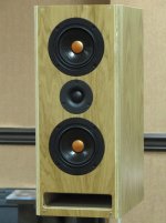
Jim Griffin's Triton MLTL conversion to a bigger box and more bass:
Jeff Bagby's original MTM Gem, in this case with rear port:
The Jeff Bagby crossover designed for the interesting CSS drivers:
The smaller MTM version frequency response:
You must excuse some of my colleagues here. They WILL quibble about EVERYTHING. 😱
It's an honour to have Mr. Bagby here too. Thankyou, Jeff. 😎
https://picasaweb.google.com/108320796621723128031/TritonMTMMLTL#
I reproduce a few images for the benefit of the sad souls who may be missing out on diyaudio membership here. 🙂
Jim Griffin's Triton MLTL conversion to a bigger box and more bass:
An externally hosted image should be here but it was not working when we last tested it.
Jeff Bagby's original MTM Gem, in this case with rear port:
An externally hosted image should be here but it was not working when we last tested it.
The Jeff Bagby crossover designed for the interesting CSS drivers:
An externally hosted image should be here but it was not working when we last tested it.
The smaller MTM version frequency response:
An externally hosted image should be here but it was not working when we last tested it.
You must excuse some of my colleagues here. They WILL quibble about EVERYTHING. 😱
It's an honour to have Mr. Bagby here too. Thankyou, Jeff. 😎
I modeled with Martin's worksheets several years before I became aware of the different units for excursion.😱 The 10.4 mm Limit for this driver, which is definitely a peak value (as is the 5.9 mm linear value) would be ~7.1 mm RMS.
Paul
Paul
Thanks for the post and noting the differences between peak and rms values. Martin's simulations do present the RMS deflection.
The Xmax specifications for the VWR126X are 5.9 mm (Klippel) and 10.4 mm (limit). Those are (I'm assuming) peak values. A reading of some of the Klippel's papers points how he has taken speaker measurements to a new level of precise definition.
Well, I am on my way to beginning the MLTL, just ordered the Acousti-Stuf and Sonic barrier from PE.
Now, if the weather would calm down, I can get to lowe's for the wood.
Hope every is enjoying the Holidays!!🙂
Now, if the weather would calm down, I can get to lowe's for the wood.
Hope every is enjoying the Holidays!!🙂
woodart,
I'm glad that you are taking the plunge. Please keep us advised on your progress. Thanks for your efforts.
Jim
I'm glad that you are taking the plunge. Please keep us advised on your progress. Thanks for your efforts.
Jim
Hi, Jim and all the others who have viewed and contributed.
Looking forward to your detailed review Jim when you think they have enough time on them.
I hope to meet with a local carpenter/builder friend shortly and have him build me a pair.
Happy New Year to all!!
Bob
Looking forward to your detailed review Jim when you think they have enough time on them.
I hope to meet with a local carpenter/builder friend shortly and have him build me a pair.
Happy New Year to all!!
Bob
I certainly will, Jim, Thanks!
Now, I just have to decide whether to buy the router stuff or have a "sort of" local do it for me.
Hey Bob, can't wait to see your build.
Oh, I meant to tell you guys I got a Marantz PM8003 for Christmas and the bass just jumped up or down hugely!! Can't wait to see how the MLTL performs.
Now, I just have to decide whether to buy the router stuff or have a "sort of" local do it for me.
Hey Bob, can't wait to see your build.
Oh, I meant to tell you guys I got a Marantz PM8003 for Christmas and the bass just jumped up or down hugely!! Can't wait to see how the MLTL performs.
In the impedance plot, the blue dash line is the native impedance of the driver; It shows the Fs just above 90 hz; it is representative of an infinite baffle mounting of the driver.
The red solid line is in-box impedance; it shows the increase in frequency of the higher peak due to the box volume; it shows another lower peak which reflects the tuning of the port/box system.
The red solid line is in-box impedance; it shows the increase in frequency of the higher peak due to the box volume; it shows another lower peak which reflects the tuning of the port/box system.
- Status
- Not open for further replies.
- Home
- Loudspeakers
- Multi-Way
- The Triton MTM Grows Legs--A MLTL Design