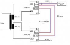
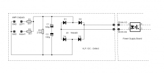
As far as I am informed, they're the SGS Ates (nowadays ST) equivalents to BC140/141 and BC160/161, resp. Use the 441's and 461's, due to their higher voltage ratings.
Best regards!
Best regards!
As I mentioned in my first post, I want to use some of the PCBs also for other AMPs by myself.
So for now I have only one complete set left. (2x Amplifiers- , 2x OutputTransistors-, 2x PowerSupply- PCBs).
In addition separately 2x PowerSupply-PCBs (These could ,-with appropriate adaptation of the components-, also be used for lower/higher voltages and currents, up to about 50V/10A).
AMP-PCB, Output-PCB: 5€/pc
Power.Supply- -PCB: 8€/pc
Plus shipping costs inside Europe.
The shipping to outside Europe probably extremely exceeds the PCB value.
If there is a further interest in boards, I would have to place new order at the PCB-plant.
In case of interest PM / EMail(via my website) me.
Last edited:
Hi...
You will likely have different requirements for using your board.
But I wouldn't call your design compressed or reduced in cost. You need one 100cm² PCB (10x10cm) for 20x TO39, while in the "original" 90cm² (7.5x12cm) is sufficient for 40x TO39.
One advantage could be that the transistors heat up each other a little less if they are further apart. Still, you can't avoid a fan.
Or you can increase the spacing even further to place clip-on heat sinks on top of the transistors, but that gets even more expensive.
The larger the surface of the circuit board, the sooner it can absorb interference and the more attention must be paid to good shielding. Perhaps not as critical on output transistors. I use groundplanes on both sides of my boards, which are ,-in the ready build device-, connected to the metal chassis of the enclosure.
Another possibility for cooling the end transistors would be to provide a solid aluminum block heat sink with a corresponding number of holes into which the transistors are inserted. The collectors are connected to the TO39 housings, so that a heat sink each is required for PNP and NPN, which are also mounted isolated in the housing. I had thought about it seriously at first, but actually the TO39s should be visible in the finished device: Housing partly with glass or Plexi etc... So it will be something with a fan.
La disposizione dei bjt rende possibile l'uso dei dissipatori per ogni bjt. 10 pezzi di dimensioni 10cm x 10 cm , presso jlcpcb.com , costano solo 5$ più spese di spedizioni...Ti ringrazio ancora per la tua idea pratica e funzionale...Grazie
Opssss...
The arrangement of the bjt makes it possible to use the heat sinks for each bjt. 10 pieces in size 10cm x 10cm, at jlcpcb.com, cost only $ 5 plus shipping ... Thank you again for your practical and functional idea ... Thanks
The arrangement of the bjt makes it possible to use the heat sinks for each bjt. 10 pieces in size 10cm x 10cm, at jlcpcb.com, cost only $ 5 plus shipping ... Thank you again for your practical and functional idea ... Thanks
Very cool project! I like the electronic fuse too. The flat tops of the cans could be in thermal contact with a heatsink plate via a squishy blue silicone sheet and you could go without the fan or put more power through them.
Good idea, xrk! I guess your way would require placing the transistors onto the PCB first, then installing the heatsink, then soldering the transistor legs?
In the (good) old days there even were plastic standoffs to keep the transistor cases with some distance off the PCB.
Best regards!
In the (good) old days there even were plastic standoffs to keep the transistor cases with some distance off the PCB.
Best regards!
I had thought of that too. In the event that I still want to do that, the transistors are already on the plastic spacers mentioned; as you can see on some of the pictures above: the blue parts under the transistors. They also help to get the transistors neatly lined up.tops of the cans could be in thermal contact with a heatsink plate
There you can also see a small "strangely" shaped sheet metal resting on three transistors. It is a thermal connection from the bias transistor to a driver.
I posted another one some time ago, part of a power supply for more voltage /current. Instead of the transistor FlipFlop there is a Thyristor to shut down the voltage. https://www.diyaudio.com/community/...r-power-amplifiers.341033/page-4#post-5879511I like the electronic fuse too
Last edited:
Inspired by this thread, and one of two others, self's Op Amp Amp, etc, I am embarking on my own ideas.
At first only output stage, but I have a number of possibilities.
2SB772 and 2SB882 in to126, or just BD139/140 in to126.
Or...maybe a strange single ended version with higher rails and BF238 or something else...
Hmmm....
At first only output stage, but I have a number of possibilities.
2SB772 and 2SB882 in to126, or just BD139/140 in to126.
Or...maybe a strange single ended version with higher rails and BF238 or something else...
Hmmm....
Hello...
There is some progress on the project.
I have completed another PCB.
It contains a speaker-on-delay with relays and the DC protection circuit.
Since it will be mounted flat against a rear panel, it also carries the input and output jacks.
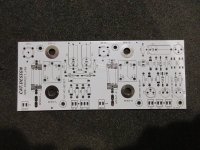
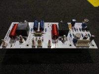
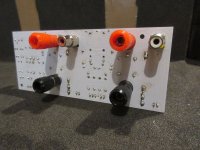
The relays look quite small, but are specified for approx. 10A DC switching current. Since the amplifier only has 30 watts, that should be enough. To be on the safe side, before I made the circuit board layout, I tested such a relay and loaded it's contacts with DC 35 V and 8 A (these values were just available with the existing equipment) and let it switch on and off, which the relay did without any problems.
But actually the relays will hardly have to switch these current/voltage values. In the event of overcurrent or DC at the amplifier output, the power supply has already switched off the operating voltage more quickly.
The primary purpose of the relays is to keep the unavoidable "switch-on bang" at the amplifier output away from the loudspeakers.
(12V Relay, typ: Bestar BS115C, Tianbo HJR-3FF, etc.)
The circuit. With TO39s. What else 😎.
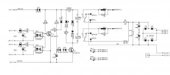
After tweaking some component values, everything now works as planned
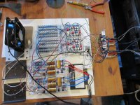
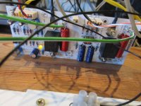

There is some progress on the project.
I have completed another PCB.
It contains a speaker-on-delay with relays and the DC protection circuit.
Since it will be mounted flat against a rear panel, it also carries the input and output jacks.


The relays look quite small, but are specified for approx. 10A DC switching current. Since the amplifier only has 30 watts, that should be enough. To be on the safe side, before I made the circuit board layout, I tested such a relay and loaded it's contacts with DC 35 V and 8 A (these values were just available with the existing equipment) and let it switch on and off, which the relay did without any problems.
But actually the relays will hardly have to switch these current/voltage values. In the event of overcurrent or DC at the amplifier output, the power supply has already switched off the operating voltage more quickly.
The primary purpose of the relays is to keep the unavoidable "switch-on bang" at the amplifier output away from the loudspeakers.
(12V Relay, typ: Bestar BS115C, Tianbo HJR-3FF, etc.)
The circuit. With TO39s. What else 😎.

After tweaking some component values, everything now works as planned


It goes on.
The last boards of the project are finished:
# Mains Power input board with filter, on/off switch, indicator LED and ground loop breaker
# Fan control for stepless adjustment of the fan speed (50-100%) depending on the power stage temperature
In the event of overheating despite full fan voltage, the circuit also sends a shutdown signal to the power supply, so that the operating voltage of the amplifier is then switched off.
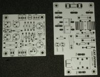
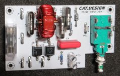
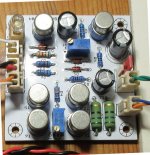
The next step is to make an enclosure that will hold all the components of the project.
The last boards of the project are finished:
# Mains Power input board with filter, on/off switch, indicator LED and ground loop breaker
# Fan control for stepless adjustment of the fan speed (50-100%) depending on the power stage temperature
In the event of overheating despite full fan voltage, the circuit also sends a shutdown signal to the power supply, so that the operating voltage of the amplifier is then switched off.


The next step is to make an enclosure that will hold all the components of the project.
to be exact:
Fan speed 50%-100% inbetween around 15°C-50°C ambient temperature (here ambient temperature means = inner housing air temperature).
Above that range the amplifiers voltage will be switched off, below from ca. 5°C the fan stops.
Fan speed 50%-100% inbetween around 15°C-50°C ambient temperature (here ambient temperature means = inner housing air temperature).
Above that range the amplifiers voltage will be switched off, below from ca. 5°C the fan stops.
- Home
- Amplifiers
- Solid State
- The TO39-AMP (40 Output Transistor Fun Project)
