Okay then ( I didn't check the file limits ).
Create an .mdat file for just the midrange and upload it ( zipped ).
My experience here ( with file sizes when running Win10 ) is that a single zipped capture/trace should be about 2.5 Mb ( at a 96K sampling rate ).
🙂
Create an .mdat file for just the midrange and upload it ( zipped ).
My experience here ( with file sizes when running Win10 ) is that a single zipped capture/trace should be about 2.5 Mb ( at a 96K sampling rate ).
🙂
Attn EarlK: The requested .mdat files can be reached on the following link:
Dropbox - ALDO - Simplify your life
Dropbox - ALDO - Simplify your life
Just in case it does not automatically download, try this link
https://www.dropbox.com/sh/pltjf4yyhphn0yl/AADXwqeeHMt2PBCPT__2oqnta?dl=1
https://www.dropbox.com/sh/pltjf4yyhphn0yl/AADXwqeeHMt2PBCPT__2oqnta?dl=1
Alain,
Thanks for that ( all good stuff ).
The REW file did download properly.
Are you going to rerun ( + then post ) an impedance file for the tweeter ?
🙂
Thanks for that ( all good stuff ).
The REW file did download properly.
Are you going to rerun ( + then post ) an impedance file for the tweeter ?
🙂
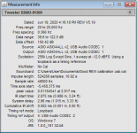
Hi to all, I am fiddling with xsim with the FRD and Zma provided earlier and want to know how to use the drivers' delay information displayed in the REW information screens below in order to enter the correct delay in xsim mod delay box . Can anyone help?
Attachments


Alain,
Here are a few things to chew on;
Here's a version that follows Paul C's ( already decided ) polarity arrangements.

Here's a variation that has all drivers with positive polarity .
Here's a comparison of the two FR's ( green has flipped polarities on the mid + tweet ),

I've attached the two XSim files for you to study ( you can see where the delays get entered within the drivers parameters ).
The delays are refined + estimated from within REW's "SPL+Phase" window > "Controls" daughter window.
🙂
Here are a few things to chew on;
Here's a version that follows Paul C's ( already decided ) polarity arrangements.
Here's a variation that has all drivers with positive polarity .
Here's a comparison of the two FR's ( green has flipped polarities on the mid + tweet ),
I've attached the two XSim files for you to study ( you can see where the delays get entered within the drivers parameters ).
The delays are refined + estimated from within REW's "SPL+Phase" window > "Controls" daughter window.
🙂
Attachments
Alain,
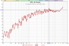
Here's the FR ( you posted ) of the ScanSpeak D2608 ( on-axis at 1 Meter ).

One can see the trace is saturated with room effects ( I believe your room needs a bunch of treatment > assuming this was taken in your listening space ).
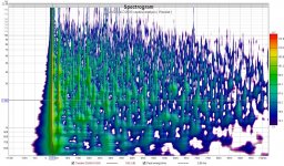
Take a look here at the following Wavelet analysis;

There's a very well defined reflection/echo/ridge ( around 6ms ) seen just after the initial signal ( which is at around 3 ms ).
- The comparative levels ( of reflection to main signa )l is within 4-5 db .
- That's way to high to be ignored by the human ear.
- The consequence here is ( with that strong a reflection ) imaging of your Tarkus project will suffer greatly ( as well as smoothness of the FR ).
That reflection also shows up in a Excess Group Delay analysis >> as all those spikes ( as seen below, pictured with 1/48th smoothing ).

- One doesn't want to see any spikes ( really ) from about 700hz upwards ( assuming one wants to enjoy some imaging from a speaker ).
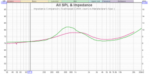
And finally, your tweeters impedance trace ( done with REW I guess ) matches the manufacturers ( close enough to be believed and therefore used ).
Here's the comaprison;

Green is original ( traced from the spec sheet ).
- Your Fs has drifted a bit upwards.
🙂
Here's the FR ( you posted ) of the ScanSpeak D2608 ( on-axis at 1 Meter ).
One can see the trace is saturated with room effects ( I believe your room needs a bunch of treatment > assuming this was taken in your listening space ).
Take a look here at the following Wavelet analysis;
There's a very well defined reflection/echo/ridge ( around 6ms ) seen just after the initial signal ( which is at around 3 ms ).
- The comparative levels ( of reflection to main signa )l is within 4-5 db .
- That's way to high to be ignored by the human ear.
- The consequence here is ( with that strong a reflection ) imaging of your Tarkus project will suffer greatly ( as well as smoothness of the FR ).
That reflection also shows up in a Excess Group Delay analysis >> as all those spikes ( as seen below, pictured with 1/48th smoothing ).
- One doesn't want to see any spikes ( really ) from about 700hz upwards ( assuming one wants to enjoy some imaging from a speaker ).
And finally, your tweeters impedance trace ( done with REW I guess ) matches the manufacturers ( close enough to be believed and therefore used ).
Here's the comaprison;
Green is original ( traced from the spec sheet ).
- Your Fs has drifted a bit upwards.
🙂
Attachments

Alain,
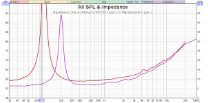
Here's a closer look at a few select areas of that Monacor mid.
Starting with it's impedance trace.

The purple trace is the makers spec ( Fs = 200hz ).
The red trace is your actual example.
- Fs is a smidge over 100hz and the actual AC impedance ( in it's passband ) is an extra 2 ohms ).
- You should measure your other example to make sure they are similar.
Others have counselled against the use of this mid.
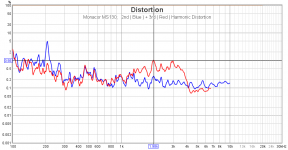
- The following distortion profile supports that viewpoint.

I personally think it's an exercise in futility to listen to any driver that has ( as part of it's distortion profile ) measured 3rd Harmonic Distortion that is greater than what 2nd HD measures at.
Additionally, the whole point of going 3-Way is to optimize driver performance over their selected range .
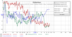
Here's an Overlay that shows the 3rd HD for all three of your drivers.
- Seen in green (within this somewhat busy pic ) is the 3rd HD of the Monacor.

Sadly, ( from 1.5K to 3K > which is within midranges bandwidth duties and contributions ) the Monacor has the worst 3rd HD performance of all 3 drivers.
OTOH, with the acoustics of your room being as "live" as they are > you might never hear any of these "drawbacks" manifest themselves.
🙂
Here's a closer look at a few select areas of that Monacor mid.
Starting with it's impedance trace.
The purple trace is the makers spec ( Fs = 200hz ).
The red trace is your actual example.
- Fs is a smidge over 100hz and the actual AC impedance ( in it's passband ) is an extra 2 ohms ).
- You should measure your other example to make sure they are similar.
Others have counselled against the use of this mid.
- The following distortion profile supports that viewpoint.
I personally think it's an exercise in futility to listen to any driver that has ( as part of it's distortion profile ) measured 3rd Harmonic Distortion that is greater than what 2nd HD measures at.
Additionally, the whole point of going 3-Way is to optimize driver performance over their selected range .
Here's an Overlay that shows the 3rd HD for all three of your drivers.
- Seen in green (within this somewhat busy pic ) is the 3rd HD of the Monacor.
Sadly, ( from 1.5K to 3K > which is within midranges bandwidth duties and contributions ) the Monacor has the worst 3rd HD performance of all 3 drivers.
OTOH, with the acoustics of your room being as "live" as they are > you might never hear any of these "drawbacks" manifest themselves.
🙂
Attachments
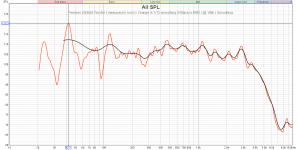
Moving on now with comments about the woofer section of your project.
Here's the FR for review;
I used ( for network design purposes ) the ERB smoothed trace seen below in Orange.

It appears that you're getting a lot of room ( cabin ) gain ( along with room modes ).
That's the main reason that the main coil ( 4.7mH ) is smaller than what Paul C. put into his network.
If you end up listening in a more controlled room ( bass wise ) then the network should be redesigned accordingly.
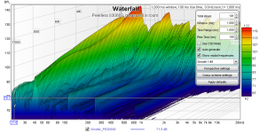
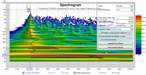
You can see the enormous effect of the bass room modes in the next couple of pics.


Some of those bass notes will just drone on and on ( assuming we are not looking at a capture contaminated with Railway or other Road Noise .
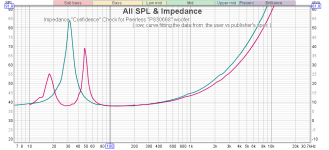
Here's a comparison of your Impedance trace to the makers spec. on the cut-sheet.
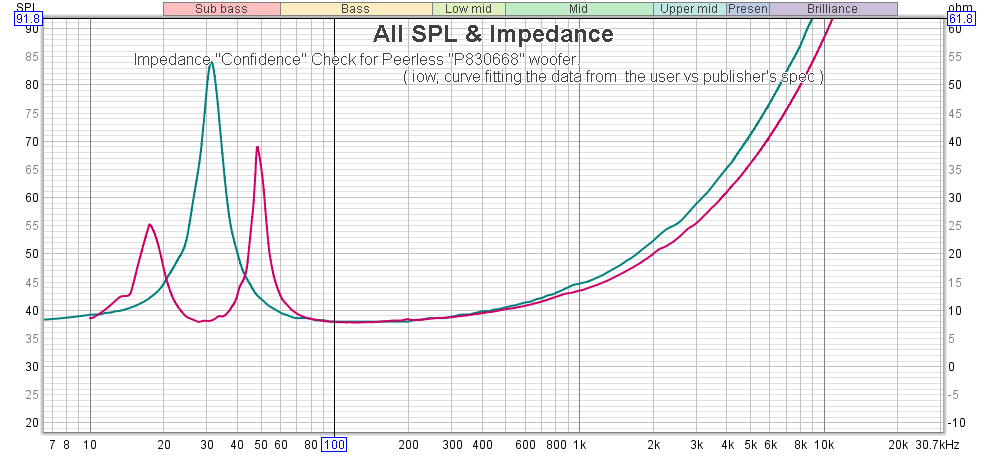
- Both track each other nicely in the area that matters >> this is the trace that gave me confidence that all your impedance captures could be used for design purposes.
🙂
Here's the FR for review;
I used ( for network design purposes ) the ERB smoothed trace seen below in Orange.
It appears that you're getting a lot of room ( cabin ) gain ( along with room modes ).
That's the main reason that the main coil ( 4.7mH ) is smaller than what Paul C. put into his network.
If you end up listening in a more controlled room ( bass wise ) then the network should be redesigned accordingly.
You can see the enormous effect of the bass room modes in the next couple of pics.
Some of those bass notes will just drone on and on ( assuming we are not looking at a capture contaminated with Railway or other Road Noise .
Here's a comparison of your Impedance trace to the makers spec. on the cut-sheet.
- Both track each other nicely in the area that matters >> this is the trace that gave me confidence that all your impedance captures could be used for design purposes.
🙂
Attachments
Last edited:
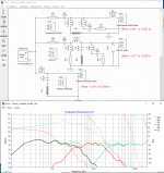
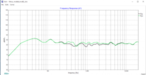
And Finally,
If you were able to clean up all the response anomalies ( box-edge diffraction ) room reflections etc. and then be able to capture traces that are much closer to those from the manufacturers >> you might be able to achieve something like the following;

I used your woofer file ( fr + zma ) but the mids and tweeters frd + zma files were derived from the manufacturers literature.
I guessed at the offsets >> and was quite close.
The increase in system sensitivity would be nice // but I wasn't able to get any of my many iterations to match this "What If" scenario.
Something to think about.
🙂
PS; You'll see the biggest difference ( comparitively speaking ) in component count in the HF section ( between "What I had to do" vs "What I would Prefer To Do" ) ..
ie; L6 is likely not needed > it's there because you don't have a calibrated mic > and thought I should flatten the response.
The LCR notch ( L7, C7, + R7 ) could hopefully be left out assuming you can clean up the baffle diffraction effects that are most likely ( hopefully ) the cause of the presence bump seen in your ScanSpeak traces.
- I would recommend experimenting with placing felt all around that tweeter ( then remeasuring ) to see if you can attenuate it mechanically.
If you were able to clean up all the response anomalies ( box-edge diffraction ) room reflections etc. and then be able to capture traces that are much closer to those from the manufacturers >> you might be able to achieve something like the following;
I used your woofer file ( fr + zma ) but the mids and tweeters frd + zma files were derived from the manufacturers literature.
I guessed at the offsets >> and was quite close.
The increase in system sensitivity would be nice // but I wasn't able to get any of my many iterations to match this "What If" scenario.
Something to think about.
🙂
PS; You'll see the biggest difference ( comparitively speaking ) in component count in the HF section ( between "What I had to do" vs "What I would Prefer To Do" ) ..
ie; L6 is likely not needed > it's there because you don't have a calibrated mic > and thought I should flatten the response.
The LCR notch ( L7, C7, + R7 ) could hopefully be left out assuming you can clean up the baffle diffraction effects that are most likely ( hopefully ) the cause of the presence bump seen in your ScanSpeak traces.
- I would recommend experimenting with placing felt all around that tweeter ( then remeasuring ) to see if you can attenuate it mechanically.
Attachments

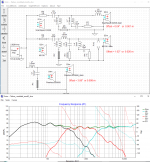
Ooops, I neglected to include the XSim file within the previous post.
Here it is.
🙂
BTW, my reference to a 4.7mH coil ( in the woofer section ) comes from this network version.
Here it is.
🙂
BTW, my reference to a 4.7mH coil ( in the woofer section ) comes from this network version.
Attachments
Last edited:
Whooa! Earlk , what an impressive work and professional approach. I am really very impressed with your hifi knowledge. When going through your detailed explanations, I must admit rank myself around 1/1000th as regards hifi knowledge.However this encourages me to learn still more, and that's the beauty of the diyaudio forum which is mutual help and knowledge sharing.I thank you very much for your precious contribution.
Now it's time for me to study in detail your writings. I surely will come back with questions.Alain
Now it's time for me to study in detail your writings. I surely will come back with questions.Alain
- Home
- Loudspeakers
- Multi-Way
- The Tarkus_Semi clone. Help in designing crossover.