Looks a little busy, and heavy!
you can have anywhere from 4 boxes to 1 box.
idealy would be two monos with each their power inside but I don't think you have the iron for that. (2 boxes)
Your left with
two monos plus single external PS. 3 boxes! My vote.
1 stereo amp plus external PS.. 2 boxes.
That Piltron chassis is huge and means the rack/shelf required will have to fight against WAF. And besides, seeing your previous chassis creations I'm sure you can do better.
cheers
Paul
paba said:Your left with
two monos plus single external PS. 3 boxes! My vote.
That would be also my preferrence. Now, the filament transformer should be in a PS or each separate in amplifier boxes?
I would put the filament supply with the mono blocks that way you will have the ability to have power switches on the monos to turn on the filaments before turning on the B+ on your external power supply.
More steps for power on and power off but better tube life.
/Paba
More steps for power on and power off but better tube life.
/Paba
Peter Daniel said:This thing is quite big.
And boring... you could stand it on an end and use it for the power supply (with iron inside)....but i know you are bound to have something much more interesting percolating in your brain 🙂
dave
Re: Re: Re: The T-Rex SET Amplifier DIY project
Konnichiwa,
Okay.
1) Dump the feedback, I calculated it noe, it amounts to 0.375db. In other words, practically NON AT ALL. Much ado in the accompanying article for no effective operation.
Saves a resistor and capacitor in the layout.
2) Get the 300B Heater Supply fixed up. There are many approaches, but you might as well get the Modules from Guido Tent and be done.
3) The 5687 SRPP may benefit from some tuning of both heater voltage (lower it to around 5.7V) and from some scaling of the resistor. The 5687 SRPP may very well be owed to the Audio Note Kit One where it is in my view and eperience the greatest sonic liability (apart from 300B Heater Supply), but I remember DO being quite fond of the Kit One.... I'd invest some time there.
Now for things that go past the basics and really get chomping.
WE Output Connection:
Connect a 8.2uF Capacitor of the higest possible quality between 300B Cathode connection and the +B connection of the output transformer. Add around 50 Ohm DCR in series with +B line. This gives around 26db better PSRR at 100Hz, a little more at higher frequencies. It actually works not only for PSU noise but also for any signal induced modulation.
In fact I found this so effective that it seems to give most of the benefits of a complex regulated supply for the cost of a single capacitor with NON of the (sonic) drawbacks regulation causes.
Easy thing to do on any self bias series feed SE Amp and always a surefire winner. The capacitor beween cathode and OPT +B connection is Ck/Mu where Ck is cathode bypass capacitor and Mu is output valves voltage gain. Use NPV (Nearest Preferred Value)
Series bootstrap biasing of driver stage:
Connect the cathode resistor of the 300B to the cathode of lower 5687 (or otherwise the driver cathode) instead to ground. Reduce the cathode resistor of the driver until the operating point folds back to what was there before (for T-Rex that would be around 180V on the anode of the lower 5687 looks like 120R would then be ideal for the lower 5687 SRPP Valve) and dump the cathode bypass cap.
This steals a little gain (around 1db) and eliminates the cathode bypass cap while actually adding VLF positive feedback compensating for the LF losses caused by undersized 300B Cathode bypass capacitor.
I would do an open plan signal chassis for the actual Amp (including the actual regulator should you keep it) and a big black box thing for the PSU, making sure to allow for long umbical cables. Make sure to place final PSU Bypasses on the Signal Chassis.
Thinks as usual, local current/bypass loops, short noise loops etc. You will be mostly there.
Peter, I may be not DO, but I have something a lot freakier (but simpler) on the drawing board for a good while now.
Care to co-operate on a kit that uses that particular angle, on a for profit basis? No Plitron Transformers except perhaps mains, 2-Chassis design with a PSU aimed at more or less "universal" operation, active load outputstage with parallel feed output from MQ (TFA2004) or S&B (if I can ever get JB to start design on them something - my bad for getting him to make interesting products - now he has no more time for interesting developments) and some rather interesting ideas on the heater supply side and drivers....
The deal (stated here openly) is one set of (prototypes?) for my use and small donation per unit sold to a charity helping children (my usual "licencing deal").
Sayonara
Konnichiwa,
Peter Daniel said:I will be definitely interested in any suggestions.
Okay.
1) Dump the feedback, I calculated it noe, it amounts to 0.375db. In other words, practically NON AT ALL. Much ado in the accompanying article for no effective operation.
Saves a resistor and capacitor in the layout.
2) Get the 300B Heater Supply fixed up. There are many approaches, but you might as well get the Modules from Guido Tent and be done.
3) The 5687 SRPP may benefit from some tuning of both heater voltage (lower it to around 5.7V) and from some scaling of the resistor. The 5687 SRPP may very well be owed to the Audio Note Kit One where it is in my view and eperience the greatest sonic liability (apart from 300B Heater Supply), but I remember DO being quite fond of the Kit One.... I'd invest some time there.
Now for things that go past the basics and really get chomping.
WE Output Connection:
Connect a 8.2uF Capacitor of the higest possible quality between 300B Cathode connection and the +B connection of the output transformer. Add around 50 Ohm DCR in series with +B line. This gives around 26db better PSRR at 100Hz, a little more at higher frequencies. It actually works not only for PSU noise but also for any signal induced modulation.
In fact I found this so effective that it seems to give most of the benefits of a complex regulated supply for the cost of a single capacitor with NON of the (sonic) drawbacks regulation causes.
Easy thing to do on any self bias series feed SE Amp and always a surefire winner. The capacitor beween cathode and OPT +B connection is Ck/Mu where Ck is cathode bypass capacitor and Mu is output valves voltage gain. Use NPV (Nearest Preferred Value)
Series bootstrap biasing of driver stage:
Connect the cathode resistor of the 300B to the cathode of lower 5687 (or otherwise the driver cathode) instead to ground. Reduce the cathode resistor of the driver until the operating point folds back to what was there before (for T-Rex that would be around 180V on the anode of the lower 5687 looks like 120R would then be ideal for the lower 5687 SRPP Valve) and dump the cathode bypass cap.
This steals a little gain (around 1db) and eliminates the cathode bypass cap while actually adding VLF positive feedback compensating for the LF losses caused by undersized 300B Cathode bypass capacitor.
Peter Daniel said:I was planning to build PS and the amp in separate enclosures. Should I go with monos or one chassis for the amp section?
I would do an open plan signal chassis for the actual Amp (including the actual regulator should you keep it) and a big black box thing for the PSU, making sure to allow for long umbical cables. Make sure to place final PSU Bypasses on the Signal Chassis.
Peter Daniel said:If the boards will be offered by Audio Oasis, it will be based on my work here and I will be designing the layout. So again, any input is appreciated.
Thinks as usual, local current/bypass loops, short noise loops etc. You will be mostly there.
Peter Daniel said:"The T-Rex is now in the public domain for the benefit of the DIY community", and since commercial rights are reserved, I will be not profiting on those boards.
Peter, I may be not DO, but I have something a lot freakier (but simpler) on the drawing board for a good while now.
Care to co-operate on a kit that uses that particular angle, on a for profit basis? No Plitron Transformers except perhaps mains, 2-Chassis design with a PSU aimed at more or less "universal" operation, active load outputstage with parallel feed output from MQ (TFA2004) or S&B (if I can ever get JB to start design on them something - my bad for getting him to make interesting products - now he has no more time for interesting developments) and some rather interesting ideas on the heater supply side and drivers....
The deal (stated here openly) is one set of (prototypes?) for my use and small donation per unit sold to a charity helping children (my usual "licencing deal").
Sayonara
Member
Joined 2002
Look dave... he's useing them transformers i was going to use and you said sucked... humm... care to change your opinion now ?
paba said:Your left with
two monos plus single external PS. 3 boxes! My vote.
I always wondered if this was really the best approach. Your source will always have a single ground reference. Splitting the amp chassis creates the potential for a voltage difference between the the two amplifiers chassis, their common power supply and the pre. Isn't it better, assuming optimum internal layout to minimize crosstalk, to use a single chassis and tight ground reference between the left and right channels and externalize a common power supply.
Konnichiwa
Peter Daniel said:
paba [/i][B] Your left with two monos plus single external PS. 3 boxes! My vote. [/B][/QUOTE] That would be also my preferrence. Now said:
Originally posted by paba Your left with two monos plus single external PS. 3 boxes! My vote.
I always wondered if this was really the best approach. Your source will always have a single ground reference. Splitting the amp chassis creates the potential for a voltage difference between the the two amplifiers chassis, their common power supply and the pre. Isn't it better, assuming optimum internal layout to minimize crosstalk, to use a single chassis and tight ground reference between the left and right channels and externalize a common power supply.
Exactly. The "common supply, mono signal chassis" is really the worst possible solution, unless the common supply shares only the Box, but the supplies are electrically seperate and NOT ground referenced.
I would vote the opposite as better, 2 Dual Mono Powersupplies with one Stereo Signal Chassis wired dual Mono....
Sayonara
Kuei Yang Wang said:I would vote the opposite as better, 2 Dual Mono Powersupplies with one Stereo Signal Chassis wired dual Mono....
Because of cost restrictions and preferable smaller size I have to share the main transformer and chokes between channels. I can go with separate regulators though.
I can also make dual channel boxes, but lets say with a possibility of tight ground reference between the left and right channels.
jleaman said:Look dave... he's useing them transformers i was going to use and you said sucked... humm... care to change your opinion now ?
I never said they sucked -- that is just your black & white interpretation. What i said was that toroids are very intolerant of DC and you have to be careful. I'd prefer C core anyway (after spending an hour or so listening to 2 very good transformer guys -- Menno van der Veen (designer of the Plitrons) & Bill Perkins -- discuss transformers, that was what i got out of the discussion.
If anyone is going to make toroids work as OPTs, it is Menno, his transformers, generally, but not universally, get very good reviews.
dave
Konnichiwa,
That means you must share grounds and thus you must use one signal chassis with well arranged ground routing.
That might be an interesting choice but does not really help where the problems are.
Sayonara
Peter Daniel said:Because of cost restrictions and preferable smaller size I have to share the main transformer and chokes between channels.
That means you must share grounds and thus you must use one signal chassis with well arranged ground routing.
Peter Daniel said:I can go with separate regulators though.
That might be an interesting choice but does not really help where the problems are.
Sayonara
Re: Re: Re: Re: The T-Rex SET Amplifier DIY project
I would surely be interested. If I manage to put this thing together, then we can discuss details of such kit. I hope that in a process of building T-Rex my knowledge of tubes will somewhat expand.
And thanks for all previous suggestions. I will make the best to try them out.
So should I go with a single regulator or one per channel, considering one box for PS , one for the amp.
Kuei Yang Wang said:Care to co-operate on a kit that uses that particular angle, on a for profit basis? No Plitron Transformers except perhaps mains, 2-Chassis design with a PSU aimed at more or less "universal" operation, active load outputstage with parallel feed output from MQ (TFA2004) or S&B (if I can ever get JB to start design on them something - my bad for getting him to make interesting products - now he has no more time for interesting developments) and some rather interesting ideas on the heater supply side and drivers....
The deal (stated here openly) is one set of (prototypes?) for my use and small donation per unit sold to a charity helping children (my usual "licencing deal").
I would surely be interested. If I manage to put this thing together, then we can discuss details of such kit. I hope that in a process of building T-Rex my knowledge of tubes will somewhat expand.
And thanks for all previous suggestions. I will make the best to try them out.
So should I go with a single regulator or one per channel, considering one box for PS , one for the amp.
Re: Re: Re: Re: Re: The T-Rex SET Amplifier DIY project
Konnichiwa,
Feel free to yell for help if you get stuck.
The Project I have been thinking off is in my books down as "the less compromised SE Amp" working title.
Intended is an active load, parallel feed, direct coupled design with some inspirations from Gary Pimm and optimised input, output and other current loops.
There will be a hybrid CCS (using KT88/6550 in case of a 300B Amp) as active anode load and a further valve based hybrid CVS (constant voltage source) in the cathode of the output valve, so all the heavy dissipation is in "glassware".
Driver will offer some options, quite possibly with an option to use some interesting DHT's as driver (I'm thinking 102D here, actually). Again hybrid active CCS loads, probably around 5687 or 6SN7 or something of the like.
Signal circuit will have exactly 1pcs Capacitor and 1pcs Resistor plus "glassware" and output transformer....
That's just to give a flavour of what I'm looking at. There will also be a rather unique PSU approach and arrangement....
If the regulator does it's job any decently to start with separating it will not give any advantage, if it doesn't then split channels will not save it.
Sayonara
Konnichiwa,
Peter Daniel said:I would surely be interested. If I manage to put this thing together, then we can discuss details of such kit. I hope that in a process of building T-Rex my knowledge of tubes will somewhat expand.
Feel free to yell for help if you get stuck.
The Project I have been thinking off is in my books down as "the less compromised SE Amp" working title.
Intended is an active load, parallel feed, direct coupled design with some inspirations from Gary Pimm and optimised input, output and other current loops.
There will be a hybrid CCS (using KT88/6550 in case of a 300B Amp) as active anode load and a further valve based hybrid CVS (constant voltage source) in the cathode of the output valve, so all the heavy dissipation is in "glassware".
Driver will offer some options, quite possibly with an option to use some interesting DHT's as driver (I'm thinking 102D here, actually). Again hybrid active CCS loads, probably around 5687 or 6SN7 or something of the like.
Signal circuit will have exactly 1pcs Capacitor and 1pcs Resistor plus "glassware" and output transformer....
That's just to give a flavour of what I'm looking at. There will also be a rather unique PSU approach and arrangement....
Peter Daniel said:So should I go with a single regulator or one per channel, considering one box for PS , one for the amp.
If the regulator does it's job any decently to start with separating it will not give any advantage, if it doesn't then split channels will not save it.
Sayonara
Peter,
I haven't had time to read the entire thread, nor have I built the circuit. In fact, I'm not even an SE guy since my speakers are too inefficient for little amps.
That said, if Broske, Olsher, and Bench have their names on it, I'd pay attention. Those guys have functioning brain cells, and that is NOT something that you'll hear me say very often. Broske, in particular, I follow. The man is clever, thorough, and well-versed in electronics. Bench has a web site with all sorts of interesting and odd things on it, all well thought out. Olsher...he's a known quantity, and all to the good as far as I know. In short, the pedigree of the circuit is impeccable.
I did get far enough in the first page or two to see some backtalk about regulated power supplies. For what it's worth, I like 'em. Just be sure to put a lot of capacitance after the regulation.
Grey
Stay the course Daniel,
John Broskie, Steve Bench and Dick Olsher are all reachable by email if you have questions. I see that others are quick to suggest improvements and changes to the plan. The classic "mine is bigger" or "mine is better" or "that design is weak here and weak there" didn't take long to pop up. It is human nature of some humans I guess. This happens over and over in history in all fields, religion, DIY audio, etc. etc.
As soon as someone puts forth an idea there is someone to there to take it down.
You have a design that was arrived at via theory, simulation and actual lab implementation, voicing and experience, plus some constraints as in all things involving the laws of physics and economics. Plus it was a group effort.
Don't get distracted and good luck.
If you need help ask, if you change the course help may be harder to find.
Paba
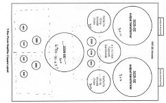
In a meantime, I did some thinking and came to conclusion to actualy use Plitron chassis for this version of the amp. I want to work fast to make the amp ready for New York Show.Two chokes and two power transformers, take the most of chassis estate, so why bother with an extra box just to contain those?
I will though make a special plate out of aluminum to hold the tubes and it will be easily removable from the rest of a chassis for modifications.
This layout was included with the parts. Is there anything that could be improved here?
I will though make a special plate out of aluminum to hold the tubes and it will be easily removable from the rest of a chassis for modifications.
This layout was included with the parts. Is there anything that could be improved here?
Attachments
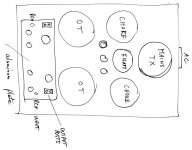
Peter Daniel said:Is there anything that could be improved here?
You could get the OPTs close to the 300Bs and the power transformer as far away as possible... Keep the AC power as far from the signal bits as possible... i wouldn't run any of the audio signal stuff to the back of the amp, just the AC power.
dave
Yeah, it seemed weired to me as well.
So I can place the mains transformer far in the back, the output transformer close to signal circuit, and input and output connector in top plate, right between the tubes and output transformers. Something like that, I guess.
So I can place the mains transformer far in the back, the output transformer close to signal circuit, and input and output connector in top plate, right between the tubes and output transformers. Something like that, I guess.
Attachments
Konnichiwa,
No offewnce meant, but it is very likely that I have build quite a few more 300B SE Amplifiers than your holy trinity together. I have also systematically (as it is my wont) evaluated the effect of many minuatae in the general design of SE Amplifiers (and others).
I made some basic observations, based on that experience, plus on some most basic circuit analysis. Based on that I retain that:
1) The Heater supply generates very high levels of common mode noice across the heater, which while giving rise to less hum than AC contain many componets of quite high order. It is a very poor solution for operating a 300B (and for most other DHT's actually), in fact compared to that type of heater supply I understand why some prefer AC heating. In fact, I suspect the Amp started out with AC filaments and was converted in a "last minute" running change.
2) The negative feedback in the circuit amounts to around 0.4db or in other words, the NFB is inactive.
Those are facts, as is the superiority of the optimised WE Connection, which in fact was actually popularised by JB.
I suggest these issues and observations in the spiri of Kaizen, or continous improvement. In other words, the "T-Rex" is quite good, BUT there remain areas where the performance has not been optimised, for whatever reasons.
Let Peter try it out and decide on the differences himself, while I often disagree with him on the relative "goodness" of certain aspects of the sonic changes a given change brings, he has a good pair of ears and is perfectly capable to make his own choices.
Sayonara
paba said:I see that others are quick to suggest improvements and changes to the plan. The classic "mine is bigger" or "mine is better" or "that design is weak here and weak there" didn't take long to pop up. It is human nature of some humans I guess. This happens over and over in history in all fields, religion, DIY audio, etc. etc.
No offewnce meant, but it is very likely that I have build quite a few more 300B SE Amplifiers than your holy trinity together. I have also systematically (as it is my wont) evaluated the effect of many minuatae in the general design of SE Amplifiers (and others).
I made some basic observations, based on that experience, plus on some most basic circuit analysis. Based on that I retain that:
1) The Heater supply generates very high levels of common mode noice across the heater, which while giving rise to less hum than AC contain many componets of quite high order. It is a very poor solution for operating a 300B (and for most other DHT's actually), in fact compared to that type of heater supply I understand why some prefer AC heating. In fact, I suspect the Amp started out with AC filaments and was converted in a "last minute" running change.
2) The negative feedback in the circuit amounts to around 0.4db or in other words, the NFB is inactive.
Those are facts, as is the superiority of the optimised WE Connection, which in fact was actually popularised by JB.
I suggest these issues and observations in the spiri of Kaizen, or continous improvement. In other words, the "T-Rex" is quite good, BUT there remain areas where the performance has not been optimised, for whatever reasons.
Let Peter try it out and decide on the differences himself, while I often disagree with him on the relative "goodness" of certain aspects of the sonic changes a given change brings, he has a good pair of ears and is perfectly capable to make his own choices.
Sayonara
Peter Daniel said:So I can place the mains transformer far in the back, the output transformer close to signal circuit, and input and output connector in top plate, right between the tubes and output transformers.
Much better :^)
Good to go... after building one, i'm sure there may well be other optimizations from experience.
dave
- Status
- Not open for further replies.
- Home
- Amplifiers
- Tubes / Valves
- The T-Rex SET Amplifier DIY project