Has anyone heard of/or seen "The "Sussex Homebrew Valve Tester" ? This looks like a really great project ! I would be very interested in others thoughts or opinions about this. It can be found by doing a simple google search ect...
I found the link, but you need to be a forum member to download the images and schematics. There's quite a lengthy thread there.
Here is all the info, but you have to be member to download or see.
The "Sussex" Homebrew Valve Tester. - UK Vintage Radio Repair and Restoration Discussion Forum
The "Sussex" Homebrew Valve Tester. - UK Vintage Radio Repair and Restoration Discussion Forum
Here is another link
Give this a look ! Hope it works > http://homepage.ntlworld.com/lez/Sussex VT/Sussex valve tester under construction.JPG
Give this a look ! Hope it works > http://homepage.ntlworld.com/lez/Sussex VT/Sussex valve tester under construction.JPG
Quite a few being built in the UK, my latest circuit is on the link below where I have added a low heater voltage regulator for testing battery valves and a heat sink fan.
Also combined the whole circuit together, I think it is better to download the image and view in MS Paint.
Still in the process of metal bashing. You only have to 'free' register on the Forum to get full access to it.
Regards
Les
http://homepage.ntlworld.com/lez/Sussex VT/Sussex valve tester under construction_4.JPG
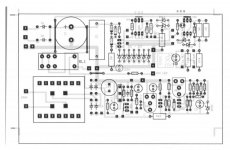
Notice I added a 50 way D connector to the PCB for easy servicing and the circuit shows the pins I chose for the various functions and signal paths.
Also combined the whole circuit together, I think it is better to download the image and view in MS Paint.
Still in the process of metal bashing. You only have to 'free' register on the Forum to get full access to it.
Regards
Les
http://homepage.ntlworld.com/lez/Sussex VT/Sussex valve tester under construction_4.JPG
Notice I added a 50 way D connector to the PCB for easy servicing and the circuit shows the pins I chose for the various functions and signal paths.
Last edited:
Also may I add that I believe the circuit boards and transformers are still available from the Forum members responsible for having them manufactured. The transformers can be supplied with primary voltage for the States. Note that the custom transformer has three separate and thus isolated meter supply outputs for powering the low cost AC powered LCD panel meters as mentioned on the Forum.
Hi-Q, Has there been any revisions made to the pcb layout to facilitate changes ? If so could you post a picture ? I have ordered a transformer but decided to wait on the pcb till all mods or additions are final.
The PCB is fine as is but does not have provision for the two extra diodes that converted the full wave two diode circuit to a bridge rectifier. These diodes are easily placed on the board however. If you look through the thread on the UK Forum you will see pictures of the pcb. Originally I believe the design used three separate boards but these have been manufactured as one large board and has to be cut down. I only cut my pcb into two pieces, effectively combining the heater relay and Gas relay on one board which I mounted on pillars on top of thee main board. You have to drill the boards yourself and so I took the opportunity to cut the track between RL2 and the Cathode connection for the Heater LED. This enables you to mount the LED current limiter resistor on board rather than at the LED.
Les
Les
- Status
- Not open for further replies.
- Home
- Design & Build
- Equipment & Tools
- "The Sussex Homebrew Valve Tester"