Niko I ve been using a BiB for supplying the digital parts of a Shigaclone transport.
Its actual performance is this
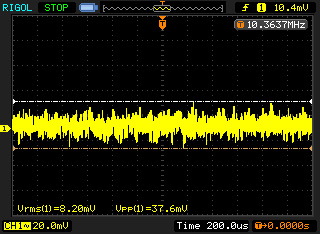
Any suggestions to make it behave better? I was thinking something like what we tried for odac
Its actual performance is this
Any suggestions to make it behave better? I was thinking something like what we tried for odac
Is this 8.2mVac of HF noise on the output of your PSU?
It's not random noise. The pp to rms ratio is too low.
It's not random noise. The pp to rms ratio is too low.
Niko I ve been using a BiB for supplying the digital parts of a Shigaclone transport.
Its actual performance is this
Any suggestions to make it behave better? I was thinking something like what we tried for odac
That's EMI eat it with a cap.
You never know exactly where from if the experimenter won't nail the source. I will show an interesting experiment shortly with a something noise I will try to photograph.
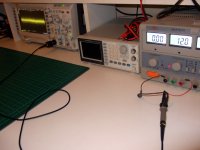
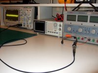
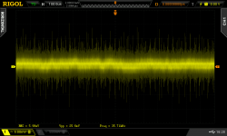
1. Bench power supply set at 12V DC. Hooked to scope on AC coupling. ~26mV pk-pk spiky noise. "What a bad PSU!" 🙄
2. Same test config. Only that the PSU is powered OFF. ~29mV pk-pk spiky noise. Ooops! 😀
3. Same config (2), opposite view.
4. Capture of config (1).
*MASTECH HY3005D3 bench PSU. RIGOL DS2000 series scope with 20MHZ bandwidth limit ON (signaled by "B" next to the vertical scale indication).
2. Same test config. Only that the PSU is powered OFF. ~29mV pk-pk spiky noise. Ooops! 😀
3. Same config (2), opposite view.
4. Capture of config (1).
*MASTECH HY3005D3 bench PSU. RIGOL DS2000 series scope with 20MHZ bandwidth limit ON (signaled by "B" next to the vertical scale indication).
Attachments

In this post, Kasuo San had the 2n4403 thermal coupled. Are the coupling between the mirror pairs?
For my learning purpose, can you shed a little explanation of why the values of resitors and caps in the sobel circuit of the reflecor is very different from the BiB? Also, what is the range of the capacitance in the vref?
Thanks!!
For my learning purpose, can you shed a little explanation of why the values of resitors and caps in the sobel circuit of the reflecor is very different from the BiB? Also, what is the range of the capacitance in the vref?
Thanks!!
Its about what has been proposed from the start, i.e. to couple the upper pair. Not he bottom pair.
They are different in analysis, Reflektor is current reaction based, so they get different termination.
2200uF is good so not to be too slow start. But you can add more if its low voltage to reach or you are patient.
They are different in analysis, Reflektor is current reaction based, so they get different termination.
2200uF is good so not to be too slow start. But you can add more if its low voltage to reach or you are patient.
Thanks, Salas, off to heating up the soldering iron now 🙂
It is going to be fun to explore !!
It is going to be fun to explore !!
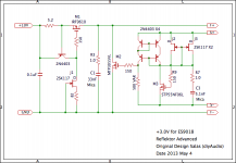
Reflektor Advanced
Hi, Reflektor lovers.
The output voltage of Reflektor is set by LED, diode and/or resistor. However, for these parts raise impedance of circuit, C2 is required. If you choose an appropriate capacitor, you will get excellent performance.
On the other hand, it is the fact that C2 limits the performance.
To solve these problems I experimented on a method with Vgs (th) of the MOSFET.
The result is big improvement. Hearing this sound, I am noticed that the sound of previous Reflektor is colored and modulated.
But this method includes some problems.
1) MOSFETs that has low impedance are not many.
Luckily STP55NF06L that I have in hand shows good performance.
2) Fine voltage adjustment is not possible.
I know that many people need +3.3V but I can't find appropriate MOSEFT yet.
Some tweak.
J2 and J3 are effective to decrease impedance of the M3. Without these JFETs it runs well.
R7 and R9 must be needed. Without these resistors parasitic oscillation is caused.
I hope that somebody will try and improve this idea.🙂
Attachments
Using a biased Mosfet as Vref is one thing, but if you find a dedicated low noise/impedance-low voltage Vref (3 legged chip) maybe you can go active ref simpler and more effectively?
Hello Kazuo Ozawa san
Congratulations for you persistent work.I too would like to build few reflektors with voltage output of 3.3V(digital) and 5V(analog) to power on my dual mono pcm1794 dac but it seems that I have to be more patient 😀
Congratulations for you persistent work.I too would like to build few reflektors with voltage output of 3.3V(digital) and 5V(analog) to power on my dual mono pcm1794 dac but it seems that I have to be more patient 😀
I did a research and found 2.048V and 4V shunt voltage references on my supplyer`s site 😀
this could be one of them Voltage Reference - Shunt Voltage Reference - LM4040A20 - TI.com
pro/cons with passive stuff?
my dac 3.3V supports max 4V and the 5V does 6.5V , don`t know the maximum for the amanero without the 5v reg.
are there any chances for the dacs to damage at 3.4-3.5V and 5.4-5.5V?
Last edited:
Using a biased Mosfet as Vref is one thing, but if you find a dedicated low noise/impedance-low voltage Vref (3 legged chip) maybe you can go active ref simpler and more effectively?
Mr. Salas always points out good point.😉
I guess it is ideal that impedance of collector of Q4 is sufficiently low and phase shift changes slowly within AF area.
For this reason, the large electrolytic capacitor may be not good.
I intended to try the same idea that you mentioned.
However the behavior of Vref chip is not ideal in many case because the internal amp is relatively comprexe. It is the reason why I did not adopt Vref chip.
In that respect, the MOSFET is very simple and near to ideal IMO.
However, I have not really evaluated Vref chip. I do not deny that it may be good enough. 🙂
Thanx
Basic concept adopted passive Vref and AC filtering (capacitor) for simplicity reasons, still exploring active reference options can bring benefits and optimization headaches but its worthy in many cases. If your voltage setting was higher some LM329 single or string with 0.8 Ohm dynamic impedance and 7uV noise would be interesting as I had mentioned in the past. Maybe just good info for other users. Is there no need for basic noise filtering with a film cap in the Mosfet ref doing some good? Because Mosfet is not considered low noise in general, but then again maybe impedance VS freq is main matter in your application. Anyway, good mod work as always, congratulations.
I did a research and found 2.048V and 4V shunt voltage references on my supplyer`s site 😀
this could be one of them Voltage Reference - Shunt Voltage Reference - LM4040A20 - TI.com
pro/cons with passive stuff?
my dac 3.3V supports max 4V and the 5V does 6.5V , don`t know the maximum for the amanero without the 5v reg.
are there any chances for the dacs to damage at 3.4-3.5V and 5.4-5.5V?
Hello, schultzsch
Oh you have already searched!
However, as I mentioned above, I think that vref chip is inappropriate for this purpose.
Thanks a lot for your contribution.🙂
Basic concept adopted passive Vref and AC filtering (capacitor) for simplicity reasons, still exploring active reference options can bring benefits and optimization headaches but its worthy in many cases. If your voltage setting was higher some LM329 single or string with 0.8 Ohm dynamic impedance and 7uV noise would be interesting as I had mentioned in the past. Maybe just good info for other users. Is there no need for basic noise filtering with a film cap in the Mosfet ref doing some good? Because Mosfet is not considered low noise in general, but then again maybe impedance VS freq is main matter in your application. Anyway, good mod work as always, congratulations.
Interesting ! I am attracted and will study further.
Mr. Salas, thanks for useful information.
- Status
- Not open for further replies.
- Home
- Amplifiers
- Power Supplies
- The simplistic Salas low voltage shunt regulator