I used 4700uF Nichicon KG with Qspeed diodes, and on the shunt PCB 220uF Elna Cerafines. Been very impressed with the latest black-skinned versions of the caps. Guessing they've been subtly improved over the years. Actually prefer these to Black Gate standards now. Looks like I got lucky with the component synergy - really powerful, but natural reproduction. Hugely involving. Dare I say it, the DAC is sounding pretty damn close to well mastered vinyl now 😉
You can't run an Aston Martin on dirty petrol, can you? Its the same with PSU juice. Must be clean. When shunt is high octane also.😉
Can you recommend MOSFETS and transistors for a 100Vin, 75Vout?
Then also for a 75Vin 38Vout?
Can we use 2sk170 in these as well?
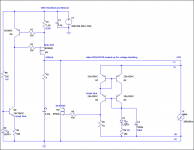
This config should do theoretically. For 75Vin & 38Vout R9 should be 24K, R6 8.8K, C2 50V. For 75Vout R6 can't be a trimmer reliably, for 38V a 0.5W trimmer will not suffer initially but better not for long term. FAIRCHILD KSA1381/KSC3503 can be found in large stockists, prefer ESTU hfe grade. Its power inefficient to use shunt regs with such constant current over load demand allowances in those voltages, watch your thermal planning and M1,M2 sinking.
Attachments
Only BJT output version there is for V1 and 1.1, the CCS is still Mosfet. I recommend full Mosfet if looking for 5V and up. 1.1 guide you can find in "SSLV 1.1 builds and fairy tales" thread, post#1
Thanks Salas 🙂 I'll take a look at it ....
Jesper
This config should do theoretically. For 75Vin & 38Vout R9 should be 24K, R6 8.8K, C2 50V. For 75Vout R6 can't be a trimmer reliably, for 38V a 0.5W trimmer will not suffer initially but better not for long term. FAIRCHILD KSA1381/KSC3503 can be found in large stockists, prefer ESTU hfe grade. Its power inefficient to use shunt regs with such constant current over load demand allowances in those voltages, watch your thermal planning and M1,M2 sinking.
Thanks Salas, at the moment there is Zener being used for both. Sure this will be much much better!
And much much hotter.😀 What is it for exactly, do you know the load's max demand in mA? This knowledge can save you heat for knowing your CCS setting limits leading to better setting decision.
You can't run an Aston Martin on dirty petrol, can you? Its the same with PSU juice. Must be clean. When shunt is high octane also.😉
Absolutely! It's a turbo-charged beast from hell now 😀
Thanks for getting me yet another step closer to the music 😎
J
Salas, newbie here. To measure the peak current used, can I insert a 1R resistor between the last smoothing cap and circuit being fed (say DAC) and measure voltage across that? Would that not be an average DC voltage? How would I estimate peak voltage (and hence peak I from V/1R)?
Do that with 1R to know, play full signal, the most DC drop you can achieve with 0dB digital peak program.
More questions if I may: Can I run several loads off 1 shunt reg (for example 74hc74 flip flop as well as a DAC (+5V))?
What about using one transformer with multiple secondaries to power several of the shunt regs?
What about using one transformer with multiple secondaries to power several of the shunt regs?
Hi all, this is my first post to this excellent thread.
I am going to construct +ve and -Ve Version 1 regulators for the input stage,VAS and pre-driver stage of a Krell clone I am building (still )and would like some advice please.
Would it advisable to build a + and - regulator for each channel eg 4 regulators or would one pair be OK for both channels?
What would be a ball park figure for biasing the CCS?
Would a 35-0-35 transformer be suitable, I want an output between 30V and 37V (Yet to be decided )
Thanks for your help.
Alan
More questions if I may: Can I run several loads off 1 shunt reg (for example 74hc74 flip flop as well as a DAC (+5V))?
What about using one transformer with multiple secondaries to power several of the shunt regs?
Yes you can put several loads on 1 regulator. But I think it's not good idea to power the logic IC and the DAC especially the analog part from 1 regulator.
No problem in my experience to use multiple secondary trans to power several regulators.
Regards 🙂
Hi all, this is my first post to this excellent thread.
I am going to construct +ve and -Ve Version 1 regulators for the input stage,VAS and pre-driver stage of a Krell clone I am building (still )and would like some advice please.
Would it advisable to build a + and - regulator for each channel eg 4 regulators or would one pair be OK for both channels?
What would be a ball park figure for biasing the CCS?
Would a 35-0-35 transformer be suitable, I want an output between 30V and 37V (Yet to be decided )
Thanks for your help.
Alan
Hi, Alan
One pair can go 90% the way, if the driver stages are heavily biased so they don't move individual current consumption too much.
150mA more than load consumption is a good point. You should decide config and know/measure the consumption of what it will feed.
The Tx sounds adequate for enough Vin to Vout distance.
Hi Salas, thanks for the reply.The drivers for the output stage will be supplied from the high current supply that also feeds the output transistors. The PCB's I have for the Krell look easy to split the tracks before the drivers, so the shunt regulator will only be feeding the input and VAS. Sorry if my wording is confusing.
Thanks
Alan
Thanks
Alan
Alright, use a small resistor in series like 0.1 to 1R when you will do the split of what you have to use the regs for, with a dvm and the drop across that resistor when you drive with a 1khz sine wave just before clip see with Ohm's law what those stages draw for current. Sum what is for each reg to feed, add 150mA for CCS setting figure.
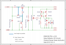
Reflektor +3.3V with STP55NF06L
The gate is fully open at last.🙂
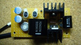
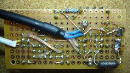
I implemented STP55NF06L into Reflektor as Salas suggested, getting great improvement.
When I used with 2SK2586, the sound was harsh. Now there is nothing, but clear ,smooth and dynamic. Especially transparency and 3-D reality is remarkable.
I have adopted four wire configuration for the first time, and surprised that the effect is very big comparing to two wire.
Zobel value is not optimized for sound quality whereas there is no oscillation at all.
Thanks Salas and other Reflektor lovers.
Lets hope it will open the Mosfet gate less capacitive at least.😀
The gate is fully open at last.🙂
I implemented STP55NF06L into Reflektor as Salas suggested, getting great improvement.
When I used with 2SK2586, the sound was harsh. Now there is nothing, but clear ,smooth and dynamic. Especially transparency and 3-D reality is remarkable.
I have adopted four wire configuration for the first time, and surprised that the effect is very big comparing to two wire.
Zobel value is not optimized for sound quality whereas there is no oscillation at all.
Thanks Salas and other Reflektor lovers.
Attachments
Great.  Zobel is 'not' optimized, or is 'now' optimized?
P.S. Is there a Z Foil resistor in the picture between trimmer and a BJTs pair?
Zobel is 'not' optimized, or is 'now' optimized?P.S. Is there a Z Foil resistor in the picture between trimmer and a BJTs pair?
Salas, in the REFLEKTOR, just to confirm:
1. that the CCS current is (2N4403)Vbe/R1?
2. And this should be = load current plus shunt current
3. The dissipation on 9610 mosfet is (Vin-Vout)*(CCS current)
4. The dissipation on 640 mosfet is (Vout)*(CCS current-Load current)
Thus when adjusting the Reflektor for different optinal currents, the best way would be to change R1?
Your help much appreciated.
Excellent, thanks,
Forgot 1 more: Total CCS should be equal to at least 150mA + load current?
And 1 more: why does Kazuo get better results with a STP55NF06L? What chnages in going from 640? What alternatives would you suggest to STP55NF06L if not available?
Forgot 1 more: Total CCS should be equal to at least 150mA + load current?
And 1 more: why does Kazuo get better results with a STP55NF06L? What chnages in going from 640? What alternatives would you suggest to STP55NF06L if not available?
- Status
- Not open for further replies.
- Home
- Amplifiers
- Power Supplies
- The simplistic Salas low voltage shunt regulator