hi Merlin
yes. i wondering if i could use 10uf instead of the 220uf on the schematic? or whats the min value should be place at the output of the salas board. as the supplied board already has 220uf on the input
thanks in advance
erwin
yes. i wondering if i could use 10uf instead of the 220uf on the schematic? or whats the min value should be place at the output of the salas board. as the supplied board already has 220uf on the input
thanks in advance
erwin
Why do you want to change, depending application it's better lytic, it's intended for digital or analog?
hi Merlin
its for analog dac out. i am just wondering if i could change it to 10uf with better quality cap on salas board. instead of 1 pcs 220uf on salas side and another 220uf on the supplied circuit
erwin
its for analog dac out. i am just wondering if i could change it to 10uf with better quality cap on salas board. instead of 1 pcs 220uf on salas side and another 220uf on the supplied circuit
erwin
If you have other 220uF at the load input I will say you can't use it at the regulator but lets's Salas to tell us something to be sure.
Hi erwin
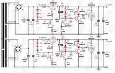
The schematic you are presenting corresponds to SSV1... it will not work with 10u on the output.
It might work with a lower value but I would not go below 47uF.
The schematic you are presenting corresponds to SSV1... it will not work with 10u on the output.
It might work with a lower value but I would not go below 47uF.
You can just use 12V input to the V1.2R and turn the trimmer down to 5V output. Use first schematic from the left in post #3200.
Better use K170 Q8 in that when targeting 5V. Will work nicer when so low.
Hi Salas,
I have 16V input and K170 at Q8, and I can only adjust Vo to min of 10.6V. Do I need to reduce the input to output 5V?
Either use lower idss for the K170 associated with the trimmer or halve the resistor directly above it. The one filtered by a plastic capacitor.
Put in a lower idss K170 and // another 27K... I can now adjust the Vo to min 5.7V.with the output connected directly to a DMM. Can I go down further by reducing the resistor to say 10K?
Hi Salas,
I change the resistor valeu to 10K and I can adjust Vo to below 5V now. Would like to check it is operating within safe/optimum design limit of V1.2R?
I change the resistor valeu to 10K and I can adjust Vo to below 5V now. Would like to check it is operating within safe/optimum design limit of V1.2R?
Regs for a TDA1541 DAC
Hi,
I'm building a 4xTDA1541A DAC; the main reasons being to try non-oversampling, to use parts I have had kicking around for a while, and to play with different iv stages. I will use off-board regs for the -15V, -5V and +5V needed. (As a separate issue there will be power needed for other parts, iv board for instance, but that's not relevant to my questions for the moment). Everything is to be p2p, essentially, so I can play around with things later.
I've searched the thread for posts about TDA1541, and read the five that turned up - it seems Salas is recommending BiB for such a situation, so I downloaded the guide, and it appears the schematic is quite similar (using leds and so forth) to the ones on the "symmetric B1" thread, which I have used (and posted about) elsewhere.
Nonetheless, I would like to try the schematic from post #3200 for the -15V (except for IRFP240 in place of IRF610 as per post #1893, simply because I had extras in my parts box), and have a few questions, both about the circuit and in general.
1. It seems that with regulators off-board, the remote sensing wires should be connected at the point the power enters the dac board, not where it leaves the regulators. I can't quite explain why this seems the right thing to do... so maybe it isn't... Is it?
2. I'm thinking of using twisted pairs from cat 5e internet cable (which I have loads of...) for the remote sensing... Sound OK?
3. I have a problem getting parts here in Brazil. I've managed to locate BF245C to use in place of 2N5459 (which I gather from the thread should be OK) but C grade BC550 and 560 are tough. I have loads of B grade, however, would these be OK, or is there some other reasonable substitute? (I wondered about 2SA970 and 2SC2240 - not sure now if the numbers are right...) I can always wait and put them on an order to Mouser or somewhere, but I only want to do that if really necessary, since it means waiting until I have enough to make the postage/packing worthwhile. (And the weeks and weeks for the stuf to arrive...)
4. For the +/- 5v regs is there a schematic for v1.2R posted anywhere? (Couldnt find one). Or is it best to use BiB? If so, please say why.
Of course, if people who understand this think I should drop v1.2R altogether please say so...
Cheers
Nigel
Bib is only superficially similar to those you mention. IRFP240 is much slower than IRF610.
1. Where power enters DAC all 4 wires should meet. That's the measuring point.
2. OK.
3. Better the BC-B than the 2SA in this situation. No BF-C grade. It will push the error amp hard and bring up noise. Break BF-C's IDSS with a source degeneration resistor down to ~4mA.
4. Use the Bib there with 1000uF Vref filters. For low 1/F noise for digital. 1.2R has things to appreciate more in higher voltage analogue CCTs. Plus can be a PITA to debug if you chance on oscillation when doing your p2p.
Hi Salas,
Thanks for the answers. A couple of points weren' quite clear - sorry if it's my ignorance...
Somewhere on the thread I read that IRFP240 was less likely to oscillate. Are you suggesting IRF610 would be better here, or that IRFP240 is adequate?
Uhhh... 4 wires means -15v sense wire meeting -15v power wire, and GND sense wire meeting GND power wire, right? Or did I misunderstand something deeper?
So BC-B is OK?
I'll read up on the BiB guide.
Thanks again
Nigel
Thanks for the answers. A couple of points weren' quite clear - sorry if it's my ignorance...
Bib is only superficially similar to those you mention. IRFP240 is much slower than IRF610.
Somewhere on the thread I read that IRFP240 was less likely to oscillate. Are you suggesting IRF610 would be better here, or that IRFP240 is adequate?
1. Where power enters DAC all 4 wires should meet. That's the measuring point.
Uhhh... 4 wires means -15v sense wire meeting -15v power wire, and GND sense wire meeting GND power wire, right? Or did I misunderstand something deeper?
3. Better the BC-B than the 2SA in this situation. No BF-C grade. It will push the error amp hard and bring up noise. Break BF-C's IDSS with a source degeneration resistor down to ~4mA.
So BC-B is OK?
4. Use the Bib there with 1000uF Vref filters. For low 1/F noise for digital. 1.2R has things to appreciate more in higher voltage analogue CCTs. Plus can be a PITA to debug if you chance on oscillation when doing your p2p.
I'll read up on the BiB guide.
Thanks again
Nigel
- Status
- Not open for further replies.
- Home
- Amplifiers
- Power Supplies
- The simplistic Salas low voltage shunt regulator