For my Disco's version of SSlvSR 1.2V Vout I matched some D45H8 (high value hfe 193), IRF9540 (high value VGS 2.97V), BC550C (high value hfe 715) & BC560C (high value hfe 619). I have lower values or have I to use these?
If I understood well matched VGS for mosfets but when is a mosfet & a bjt can't be matched so I have to use high values VGS & HFE? or isn't necessary? I need this information also for BiB.
Mosfets match to Mosfets for same positions, BJTs match to BJTs for same positions in a double mono or symmetric for instance. If you have just one reg you may choose high hfe for the BJTs and that's it.
thank you to salas
well I just got my phono preamp hooked back up with your bib regulator. I replaced a point to point regulator of your design that I built about a year ago when I built the preamp. Also your design. It was quiet before, but now you can't even tell it's turned on....I consider myself a good mechanic, but I am just starting to be able to comprehend how stuff really works. I wanted to say thank you for the time you and many others spend designing, sharing, and explaining your designs in a way that even I can follow.....
well I just got my phono preamp hooked back up with your bib regulator. I replaced a point to point regulator of your design that I built about a year ago when I built the preamp. Also your design. It was quiet before, but now you can't even tell it's turned on....I consider myself a good mechanic, but I am just starting to be able to comprehend how stuff really works. I wanted to say thank you for the time you and many others spend designing, sharing, and explaining your designs in a way that even I can follow.....
Attachments
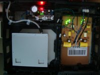
Hi evanc
Nice build you have there. Would you care to post some details so we can learn with your experience ?
What cart are you using ?
What is inside the metal box ?
How many dB does your Riaa amplify ?
What are the values of the Auricaps on the riaa filter ?
Are the red resistors Takman Carbons ?
Only one shunt for both channels ?
Sorry for so many questions but I can not help myself asking 🙂
Last edited:
Hi Salas
I am now preparing a +- 10V PSU for the new DCB1 build.
I am using V1 shunts with 10uF Ampohm over 8k2r // 100kr trimmer for Vref.
In this case the CCS is a k170 with Gate and Source together to GND. Voltage is set by adjusting the 100kr trimmer // with the 8k2r on top.
It is adjustable but very difficult to set.
In my other builds (V1.2 and V1.2R) I am using a much higher resistor for Vref (around 30kr) and adjustments are done with a 1kr trimmer on the source leg of the k170 CCS.
In these cases, Vref is easily adjustable. Can I implement the same in the V1 build ? (A bigger resistor bypassed with the 10u film cap and a small 1k trimmer between the k170 Source and GND?)
well I just got my phono preamp hooked back up with your bib regulator. I replaced a point to point regulator of your design that I built about a year ago when I built the preamp. Also your design. It was quiet before, but now you can't even tell it's turned on....I consider myself a good mechanic, but I am just starting to be able to comprehend how stuff really works. I wanted to say thank you for the time you and many others spend designing, sharing, and explaining your designs in a way that even I can follow.....
Very good. You are welcome.
Hi Salas
I am now preparing a +- 10V PSU for the new DCB1 build.
I am using V1 shunts with 10uF Ampohm over 8k2r // 100kr trimmer for Vref.
In this case the CCS is a k170 with Gate and Source together to GND. Voltage is set by adjusting the 100kr trimmer // with the 8k2r on top.
It is adjustable but very difficult to set.
In my other builds (V1.2 and V1.2R) I am using a much higher resistor for Vref (around 30kr) and adjustments are done with a 1kr trimmer on the source leg of the k170 CCS.
In these cases, Vref is easily adjustable. Can I implement the same in the V1 build ? (A bigger resistor bypassed with the 10u film cap and a small 1k trimmer between the k170 Source and GND?)
I would use a lower value trimmer //8k2 as it is firstly. The other adjustment produces more drift, but it was implemented for affording higher Vref resistors for filtering lower in frequency with just a film cap. A ''quality'' decision VS better drift.
hi all,
i just want to share my experience on newly made diy resistor that are replacing the ''current setting'' power resistor. i was curious to see if a piece of wire could enhance the sound, so i wound a mobius loop in a certain pattern to minimise inductance and capacitance a bit and so far these beat my pair of metal oxyde 3w resistor (total 6w). i wound 4 meter of some 32 awg copper magnet wire (around 2 ohm for around 500ma) and it gets way less hot than the MO resistors. i guess this may acount for the increase in sound quality i noticed. thought the lenght of the wire and the distance between turns is not that great, i believe there is some level self inductance and parasitic capacitance which i cant tell if it has an audible impact or not. i m curious to know if there could be any downside to too much inductance and capacitance on that resistor. maybe someone more educated could tell?
next step i ll try bigger gauge for better thermal stability in a parttern alike ECdesigns diy resistor.
note that i m using a few LC stages before the reg so one might not hear much difference if he has some RC filters before with noisy resistors.But for me the difference was not subtle.
has anyone ever tried diy resistors before?
http://www.diyaudio.com/forums/digi...ding-ultimate-nos-dac-using-tda1541a-357.html
Last edited:
You mean those around the double crown grade NOS chip in a picture down the linked page? What current setting does it do? Has to do with the TO-220s next to the twin towers mobius?
-yes the resistors are the towers with the white plastic gear-like top and bottom.
-500ma on mine so around .5w
- not sure what you mean by ''Has to do with the TO-220s next to the twin towers mobius''
- from what is written above the picture, i m not too sure they are mobius loop. dont think it s needed for this pattern.
-500ma on mine so around .5w
- not sure what you mean by ''Has to do with the TO-220s next to the twin towers mobius''
- from what is written above the picture, i m not too sure they are mobius loop. dont think it s needed for this pattern.
I guess that those diy resistors are achieving very good ppm and that should be beneficial. I was asking about what those in the picture do in regard to those TO-220 packages near them. Is there a picture of your application?
P.S. He states ''Honeycomb Mobius construction'' though.
P.S. He states ''Honeycomb Mobius construction'' though.
ok i think i get it 🙂
i dont know what is the link between the to-220 but the diy R are the I/V resistors.
my application is 2 of your v1.1 reg modded to feed 3.3v es9022 and clock.
yes i also think ppm is very good. the surface exposed to air is very high and it acts like a radiator nothing less.
here is the non inductive pattern form ECdesigns' resistors from what i deducted. each ''diamond'' form a non-inductive loop. maybe i m wrong?
Attachments
Last edited:
Maybe you could skip the hassle by using some superior spec than MOX ready made resistor with good enough results?
yes maybe. i d have to buy some for comparison. for sure it would be simpler🙂. but you d need one hell of a big resistor to achieve the same resistor temperatures.
and yes he clearly states MOBIUS a handful of times...i ll have to check that.
also as he said if you join the 2 ends of the wire and putting it on some coil former (treating it as a single wire), it could do the trick. at the expense of too much capacitance maybe?
and yes he clearly states MOBIUS a handful of times...i ll have to check that.
also as he said if you join the 2 ends of the wire and putting it on some coil former (treating it as a single wire), it could do the trick. at the expense of too much capacitance maybe?
Last edited:
I remember Merlin was saying that he could pick some subjective improvement for that CCS setting resistor if substituted with best quality in the 1.1 Bib build thread also. Because it does not ''see'' the gate, trying out different there, more or less capacitance, don't know, but I don't think it can give oscillations at least. Watch out for possible placebo non the less.🙂
yes that pacebo guy can strike when you least expect it 🙂
i hope someone who has tried something like i did will chime in...
i hope someone who has tried something like i did will chime in...
I did not try DIY resistors but I am willing to do it.
Please post some literature and a sensible way to make the needed calculations.
IMO Vref resistor quality is determinant in the final shunt tone.
Please post some literature and a sensible way to make the needed calculations.
IMO Vref resistor quality is determinant in the final shunt tone.
I would use a lower value trimmer //8k2 as it is firstly. The other adjustment produces more drift, but it was implemented for affording higher Vref resistors for filtering lower in frequency with just a film cap. A ''quality'' decision VS better drift.
Using a 8mA idss jfet for the ccs I should use a 1k25r to get 10Vout right ?
In the V1.1 you use leds... how can I use those to set 10Vout ?
- Status
- Not open for further replies.
- Home
- Amplifiers
- Power Supplies
- The simplistic Salas low voltage shunt regulator