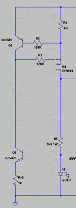
only to clarify, what should be close to what exactly? as it is now, my whole ccs fits a rectangle of 4cm by 2cm, this seems within reason to me...
i will also try the 82r gate stopper
Hi!
I made my own design, and now it works. It's optimized for the use as an onboard regulator. Now to look for a matching heat sink.
The thin scope trace indicates a very low output noise and absence of (low level) oscillations.
From this behaviour It seems to be better than my former approaches, and even better than the super reg boards I have.
Congratulations, Salas!
It's purpose is to serve as a phonopre psu.
Rüdiger
Great. We must always persist for solutions. But what was the problem? Rearranged the layout, something reversed, or changed some substitution component?
I don't know. Obviously, the CCS part and the shunt/cfp arrangement of THKL's desgin was ok, and the error-amp part was not, or I had an unfindable mistake in it. With the re-arranged layout of the error-amp it works now (with all the mentioned parts, BC560 all along and 2sj103 instead of 2n5457, all else being equal). bypass cap for the 'reference' is a 2.2uF film cap, output bypass is a mediocre generic 330uF El-cap. I will test other arrangements as well.
Rüdiger
Rüdiger
OK. See to always have some ESR if with an output lytic or some technically added R if with a film output cap. I hope you will appreciate the regs subjectively too. Thanks for informing us your results.
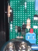
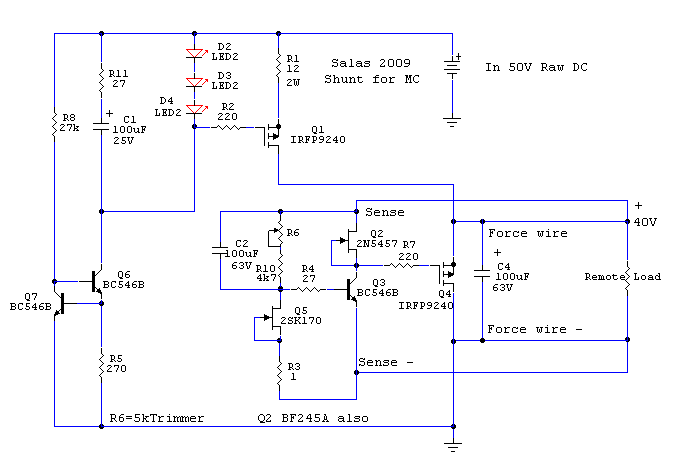
Hello, I'm making the following design
But I have problems...
With 50v raw DC input I get about 20v output and the leds are not lit...
Any suggestion on what to check would be very helpful 😱
But I have problems...
With 50v raw DC input I get about 20v output and the leds are not lit...
Any suggestion on what to check would be very helpful 😱
Ok problem solved I had forgotten to connect C1 with the leds...
But now a new one came up... R1 (12R 2W) is overheating an finally burning in less than 5 seconds 😱
But now a new one came up... R1 (12R 2W) is overheating an finally burning in less than 5 seconds 😱
Probably a burned or reversed Q1 Mosfet. This is V1, made so many times by very many people, so nothing to think beyond troubleshooting your connections against the schematic and to look for destroyed components due to powering it up when built wrong initially.
heat sinks
@Salas
Can cut this big heat sink in small parts to use in the regs., I mind to divide in parts with exact weight like your advice heat sink 443 gr?
Photo big heat sink:
Photo your advice heat sink:
@Salas
Can cut this big heat sink in small parts to use in the regs., I mind to divide in parts with exact weight like your advice heat sink 443 gr?
Photo big heat sink:
An externally hosted image should be here but it was not working when we last tested it.
Photo your advice heat sink:
An externally hosted image should be here but it was not working when we last tested it.

If the LED is not lit strongly then some oscillation in the ccs. Not the bjt type. If the cascode bjts aren't tight to the ccs control bjt is the reason. If you can kick start the reg by touching the ccs gate stopper with a probe then that's it. If it gets warm, it may kick start alone at a point, and then works clean. You may also go 82R gate stoppers for 9540 series. They seem more capacitive than in data, since their ygfs is actually stronger than 9240s.
I have been here before and I found the finger "kick start" by myself once.
The ccs led in V12 do not glow 1/2 the brightness as the one in my v1 implementations.
Lowering the voltage divider resistors from 5k6 to 3k3 did not improve much in terms of led glow in my 37 or 28v shunts.
I can not hear any noises and v12 fullfilm is clearly the winner in terms of speed, detail and dynamics, but in my last build I am registering a slight hum that might be caused by ccs instability.... and gave me a hard time shielding every power line in my build.
My ccs layout is not as closely built as you showed .... can this be the origin of my issues ?
Ricardo
Can't be sure, you may rearrange it and see. In my experience its either sure oscillation or clean. Not some little hum. But it can be a low level oscillation in yours. Without a scope we can only guess. The LED here is about 3-5mA depending on Vout and resistors used, not at idss like in V1, so don't expect a glow like in V1, but it should not be too weak too.
One thing you can do is go one transistor if you can not solve it by layout as it is, and see if the LED glows stronger. It will be much easier to tuck it together. It loses some performance but still very cool. If it will work good and you really had a problem, it will be better than before. Then you will know if the little hum was related or not too.
One thing you can do is go one transistor if you can not solve it by layout as it is, and see if the LED glows stronger. It will be much easier to tuck it together. It loses some performance but still very cool. If it will work good and you really had a problem, it will be better than before. Then you will know if the little hum was related or not too.
Attachments
It is good to know we can do the ccs with only one lower bjt but the performance is so good right now that I do not wish to compromise.
As I already built six v12 with EL output cap with exactly the same pcb layout and these work perfectly, I guess the problem might be in the big output cap and it´s long legs.
Is there anything I can do to minimize Loop area ?
PS: I am in the market for a good low cost oscope 🙂
As I already built six v12 with EL output cap with exactly the same pcb layout and these work perfectly, I guess the problem might be in the big output cap and it´s long legs.
Is there anything I can do to minimize Loop area ?
PS: I am in the market for a good low cost oscope 🙂
Try film 10nF caps in parallel to big output caps, if possible use the same like I sent you.
Last edited:
Do you believe bypassing the output cap might reduce hum ?
I did that when I experimented with a lesser quality EL output cap and got heavy instability.
I did that when I experimented with a lesser quality EL output cap and got heavy instability.
Last edited:
I used as per Salas advice in mine NJFET RIAA at the input gnd RCA to gnd chassis with very good result, also used the same in mine Erno Borbely balanced preamp with same good result. If I remember well one time Salas told me that use it to avoid hum in long legs film caps.
I don't know the results for your new all film regs.?
I don't know the results for your new all film regs.?
Last edited:
This time you got technically added R outside the cap. If you will bypass any film cap there it will not have an impact on circuit's parameters. Its not a matter of the reg design if you got some hum. Its a whole phono build and regs layout. If you don't target its origin we are talking guesswork. If you had no problem with lytic output, add one across the output film (not including the +0.5R), so to see if you simply need more uf there or not. If nothing changes then its probably pick up due to widened loop area. I use compact radial MKT or MKP caps in V1.2 that can be altered subjectively by MKP1837, Ero KP, FT-1 Teflon etc. bypassing.
- Status
- Not open for further replies.
- Home
- Amplifiers
- Power Supplies
- The simplistic Salas low voltage shunt regulator