OK, thanks for that guidance. I copied and pasted the info into my notes on the SSLV.
I'm sorting things out with Tea now. It looks like if I want to have the option to put together SSLV supplies for all three projects that I will need to order 3 of the SSLV boards in order to have a positive and negative rail for each supply.
The mini DSP can run anywhere from 5-24Vdc and needs 150mA according to the manual. The BoozeHound Phono runs on 18-24Vdc and supposedly uses less than 50mA, but I think it's prudent to give it the ability to supply 100-150mA.
The ZYX CCP-1 needs 12V, and I'll be running the mini DSP at 12V and the BoozeHound at 18V. So I guess I will need 3 each of the positive and negative rail mini kits with the IRF9530/530 option? I realize there are other items I will need to come up with to set the voltage for each supply properly.
Each board has two positive and one negative sections. Its also readily breakable along each section because it has a V groove. You will only need utilize and populate the positive sections since all the gear you listed accept monopolar (+/0) power. So it takes two boards to collect three positives. Save the remaining sections for future projects that may need bipolar (+/0/-) symmetrical rails.
You don't have to replace the IRF9610 current source by the more robust but slower IRF9530 because you don't need any excessive current setting. The IRF9530 shall remain in the shunt output position only as in the standard design.
The mini DSP 2x4 will be drawing 150mA at 5V and about 75mA at 12V as I read in the company's support forum. I have one too but I never bothered to measure its exact consumption because it wasn't getting hot and a small wall wart could easily power it. The Boozehound is a light load too as you said.
Phew, lots of drawing.
Hello Salas,
In V1.2R up to 45V positive:
Q3 and Q4 are BC550C
But in V1.2R minus (-45V version):
Q3 and Q4 are BC560B
Is this correct? I thought Q3/Q4 in V1.2R minus should be BC560C (instead of the B version)....
Thank you
I probably had silverface Philips BC560B from some small NOS stash at the time in the prototype but it shouldn't matter for those positions. Use C as well.
can we use J113 N channel Jfet as I have some in stock it also uses Process 51.
http://www.mouser.com/ds/2/149/J113-889353.pdf
http://www.mouser.com/ds/2/149/J113-889353.pdf
I find that they usually have Vp 1-2V & Idss 10-20mA so not useful for straight substitutions in these designs. If you got any samples that measure around 0.6V Vp they may do.
Not for all places in those designs, higher VGS(off) than workable under one Vbe is the main obstruction although Idss is tame 5mA to 11mA usually. Even the 5mA ones have 0.8V VGS(off) also named pinch off voltage (Vp). I measured about 30 samples. This type is employed in my DCG3 line/hp preamp's DCSTB companion PSU.
so you don`t recommend the PF5102?Not for all places in those designs, higher VGS(off) than workable under one Vbe is the main obstruction although Idss is tame 5mA to 11mA usually. Even the 5mA ones have 0.8V VGS(off) also named pinch off voltage (Vp). I measured about 30 samples.
which other Jfets would you recommend apart from 2sk170 which are in TO92 package in the regulator?
Salas Shunt Low Voltage Regulator V1.2
I need to build this excellent shunt regulator V1.2 and here is the schematic that i connect together in paint so if someone can check if i connect right all before i do PCB Layout?
And need advice:
1. Input is 24VAC which gives around +/-34VDC before rectifiers and filter capacitors with resistora...i need to get output +/-24VDC (200mA).
So what i need to change in schematic to get desired output voltage and current?
2. Can i change BC550C/BC560C with 2SA970/2SC2240 to get better output impendance and noise? (I have both at home)
3. Can i add on SK104-25,4 heatsink both MOSFET so i need then on heatsink and smaller PCB or do i need to put separate each MOSFET on each heatsink?
4. My BJT Preamplifier draws 30mA so i guess it is ok to lower the input current from 200mA to 100mA to get same charactersistics like simulated in LTSpice or i need to leave it 200mA? 6,8R is then for R11 & R15 needed to get 100mA current? 0,66 / 6,8R = 97mA
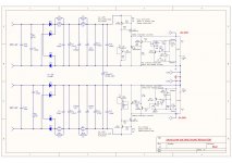
And here is the schematic that i added snubler for toroid on start limit, bridge rectifier and RCRC filter to get @100Hz -75dB PSSR (if i don't use RCRC only large C i get PSSR -57dB so i use RCRC because it is excellent filtering device)
I need to build this excellent shunt regulator V1.2 and here is the schematic that i connect together in paint so if someone can check if i connect right all before i do PCB Layout?
And need advice:
1. Input is 24VAC which gives around +/-34VDC before rectifiers and filter capacitors with resistora...i need to get output +/-24VDC (200mA).
So what i need to change in schematic to get desired output voltage and current?
2. Can i change BC550C/BC560C with 2SA970/2SC2240 to get better output impendance and noise? (I have both at home)
3. Can i add on SK104-25,4 heatsink both MOSFET so i need then on heatsink and smaller PCB or do i need to put separate each MOSFET on each heatsink?
4. My BJT Preamplifier draws 30mA so i guess it is ok to lower the input current from 200mA to 100mA to get same charactersistics like simulated in LTSpice or i need to leave it 200mA? 6,8R is then for R11 & R15 needed to get 100mA current? 0,66 / 6,8R = 97mA
And here is the schematic that i added snubler for toroid on start limit, bridge rectifier and RCRC filter to get @100Hz -75dB PSSR (if i don't use RCRC only large C i get PSSR -57dB so i use RCRC because it is excellent filtering device)
Attachments
You can't go >28V Vin because Q3 & Q6 won't take it. If you got other low noise type with >30V VDS max and VGS (OFF) >1.5V you could.
The BC transistors are working in practical layout with enough phase margin in there, for other types you would only know after you have tried them.
You should insulate the Mosfets.
100mA is OK.
The BC transistors are working in practical layout with enough phase margin in there, for other types you would only know after you have tried them.
You should insulate the Mosfets.
100mA is OK.
I try to search for JFET that have VDS > 30V and VGS (OFF) > 1.5 but i find only 30V VDC so i think it is difficul to find some...
Could you post link or post number where is V1.2R version of schematic? This theme have so many posts so that i could not find the V1.2R.
Could you post link or post number where is V1.2R version of schematic? This theme have so many posts so that i could not find the V1.2R.
And i found J111 it has:
VDG 35V
VGS -35V
VGS (OFF) -3.0V(min) and -10.0(max)
Is this good replacement for 2N5459? Or i take 2N4119A?
2N4119A Datasheet
Calogic - datasheet pdf
J111 Datasheet
http://www.farnell.com/datasheets/2...13.752890756.1516657423-1722369814.1512330143
What is better or i need to go to new schematic V1.2R if you could post link?
Hi,
Im planing to use a Salas Shunt for a Juma BF862 Preamp tha Salas publisged in post #84
I think this is a kind of simplistic Salas low voltage shunt regulator so i hope im doing right here.
It will be my first Salas Shunt so there are a few questions i hope to get anwered here.
1. How much dissipation will there be from Q1 an Q5. I plan to use this one from Fisher. OK?
2. What kind of Resistor should be used in order of Watt especially for R1?
3. Is there an option to regulate the voltage outcome (in/decrease R10, R8?)?
4. Did I forget something that i should attent?
Regards Christoph
Hi all, it seems I have broken my reflektor d mini 🙁 . I got a 24v load into the wrong end of my DAC so it will have touched the output of the reflektor d and now the LEDs on the output of both of my reflektor d mini are not lit any more. Presumably I have blown a component, but can anyone guess as to which one is likely to be faulty or how to test them?
Thanks,
James
Thanks,
James
Check vgs and vbe on mosfets and bjts, rds for jfets. Few V for mosfets, sub V for bjts, few decades of ohm for jfets. Its probably the output mosfet or the jfet near it that has been compromised, but not necessarily so.
Hi,
Im planing to use a Salas Shunt for a Juma BF862 Preamp tha Salas publisged in post #84
I think this is a kind of simplistic Salas low voltage shunt regulator so i hope im doing right here.
It will be my first Salas Shunt so there are a few questions i hope to get anwered here.
1. How much dissipation will there be from Q1 an Q5. I plan to use this one from Fisher. OK?
2. What kind of Resistor should be used in order of Watt especially for R1?
3. Is there an option to regulate the voltage outcome (in/decrease R10, R8?)?
4. Did I forget something that i should attent?
Regards Christoph
1. It will be what current they run times what voltage they have across them. The input mosfet will dissipate for the full set current limit (circa 200mA) times the voltage drop from raw dc to regulated output. The output mosfet will dissipate the set limit minus the load's current draw times the output voltage. Calculate the above and use large sinks enough not to go above 60C however they gonna be installed i.e. will it be free air, ventilated box, fully closed box, forced air cooling.
2. 0.5-1W
3. Make R10 a 10k trimmer (rheostat mode)
4. No. If you want to change the CCS current the formula is VbeQ2/R1.
Thanks for the help. Turns out when I pulled things apart for diagnosis, the reflektor regulators are just fine when not connected to the DAC, so that is good news. Both channels of my DAC chips are fried though, not so good news...Check vgs and vbe on mosfets and bjts, rds for jfets. Few V for mosfets, sub V for bjts, few decades of ohm for jfets. Its probably the output mosfet or the jfet near it that has been compromised, but not necessarily so.
Thanks again,
James
- Status
- Not open for further replies.
- Home
- Amplifiers
- Power Supplies
- The simplistic Salas low voltage shunt regulator