I bathed the DACT Type 21 Stepped Attenuator in methylated spirits and tuned the pot for a dozen times. When dried, I used some RS Component (expensive) contact cleaner to spray it around and used electrical tape to wrap around the opening area. Soldered it back to the preamp. I turned the pot and didn't hear the cracking sound anymore. So the cleaning was successful. And now the good sound is back!🙂
I then got an email from the ebay seller that "If there are dust inside or bad contact, I always use "3M Contact Cleaner" to clean it. Not recommended to use spirit or alcohol for electrical contacts. Some buyers said that they use "Hot Shrink Tube" to wrap this Attenuator to avoid dust.". It was too late but never mind.
A big lesson has been learned. Forget about the expensive genuine ALPS pot, despite having measured it and found reasonably tight tolerance between channels. Quite an obvious difference in sound quality. These ebay DACT type 21 pots are highly recommended. Thanks for Salas recommendation.
Regards,
Bill
THX for info.
I have that DACT instead Blue Alps in my tube DAC for two years with no problems. I bought few, just for reserve.
Compared to Alps this DACT doesent have any annoying artifacts in highs, nore it gives to sound some kind of pompousness, that Alps was showing in my system.
I know someone, who did the opposite.
He changed that DACT for Alps in very similar DAC as mine and after that, he spended a bunch of money for Duelund and Mundorf top end caps to "solve the harsh and annoying artifact problem in highs" and even now he still have the same "artifact" problem and more bitter character then before Alps implementation.
That DACT can reveal some slight harshness on a signal path caused with some other passive components or cables.
Remedy.
Just put somewhere on signal path or in voltage regulator, or in xover for tweeters, russian PIO K42-2 caps instead MKPs and enyoy in civilised sound.
Too much of K42-2 can make sound to dull, just a pair or two, will wipe off harshness and reveal bit more depth and can i say, they "make" sound more smooth and liquid.
K42-2 are very fast puppies, so dont be affraid for your transients, they even slightly better them.
Last edited:
Are you talking about these ? DACT Type 21 Stepped Attenuator Potentiometer 50K 300B - eBay (item 120473999989 end time Mar-20-11 11:05:02 PDT)
I wonder why they are called DACT : DACT audio attenuators
I see both use SMD resistors.... but what type of resistors ?
I wonder why they are called DACT : DACT audio attenuators
I see both use SMD resistors.... but what type of resistors ?
Last edited:
VALAB 23 Step Attenuator Potentiometer 20K Stereo Log on eBay.ca (item 300420653208 end time 19-Mar-11 03:48:37 EDT)
I've been using one of these in my DCB1 for some months now. It works extremely well most importantly sounds good; certainly a step up from the PEC pots.
I've been using one of these in my DCB1 for some months now. It works extremely well most importantly sounds good; certainly a step up from the PEC pots.
Do you know what type of resistors are used in those pots ?
SMD Vishay
I don't know if are MF, the problem with series attenuator is that each step you do more noise because you add other resistor in the signal way, the advantage over shunt is that not change the input impedance, best is ladder type.
I had DACT 10K & now I'm using Shallco 10K shunt all Shinkoh resistors & is far better.
I had DACT 10K & now I'm using Shallco 10K shunt all Shinkoh resistors & is far better.
Mods?
Hi,
I have running Salas v1 regulator for in my JHL headphone amplifier powering both channels. CCS is set for 340ma. Sounds superb, maybe little dark, but it could be headphones or amp itself.
As I was reading the whole thread I noticed I have few little differences in schematics I have used.
Referenced to positive scheme:
First, should I bypass the CCS leds with 100uF elyt? Some schematics have this bypass some not.
Second, should I put 10r resistor between Q3 2SK170 FET and ground?
Third, output cap is only 47uF, should I raise it to 220uF as on the other schematics or lower is better?
Thank you very much.
What CCS Mosfet type and have you added remote sensing? RS helps resolution further. That CCS leds capacitor helps the PSRR but not too drastically in practice. You may check subjectively with or without it. That 10R was working towards better transients with the initial V1.0. If you take out the CCS Leds cap, take that out too. 47uF is good when your tone in general tends to darker.
Forgot to add my schematics...
OK, now I see what you made. 9610 is nice for CCS. Its OK as a whole. You may short R3. Use remote sensing or use very short strong cables. C6 different brands to try, some can brighten up your tone. How high voltage for the JLH?
Thanks for reply. So I can leave the schematics as it is and experiment with output cap - smaller darker sound and bigger brighter sound I suppose.
Input voltage is +-18V and output is +-10V.
Input voltage is +-18V and output is +-10V.
You can experiment with C6 which is across the trimmer and Led. That one you can make from 47 to 220uf, change brands, esr, bypass with poly even. The output one never bypass with poly or mkt and you can play between 47-220u and qualities. But not super low esr please, to stay stable. Can't comment on how it will affect the total of your components, since I can't experience them, but I know its effective enough. You tune. Always use remote sensing 4 wires for best resolution.
Hi Salas,
I would like to build your shunt regulator psu for T-amp. The current draw will be around 200mA.
Will Q1 and Q4 be hot under this current consumption ? Will 0.5W rating resistors be suitable for this application ?
Also in your design, the input voltage is 20V while the output is 12.6V. Can I use a higher input voltage say 22V to get the same output voltage of 12.6V ?
Thanks for your input in advance.
YC
during which operating conditions is the current draw 200mA?.... shunt regulator psu for T-amp. The current draw will be around 200mA.
Are there any operating conditions when the current draw from one or other supply rail is less than 200mA?
Are there any operating conditions when the current draw from one or other supply rail is more than 200mA?
Hi Salas,
I would like to build your shunt regulator psu for T-amp. The current draw will be around 200mA.
Will Q1 and Q4 be hot under this current consumption ? Will 0.5W rating resistors be suitable for this application ?
Also in your design, the input voltage is 20V while the output is 12.6V. Can I use a higher input voltage say 22V to get the same output voltage of 12.6V ?
Thanks for your input in advance.
YC
200mA for a T-Amp? Maybe just at cruising level for the 15W model. Use a current meter in series with your now supply and play at full tilt tracks with strong dynamic range on your most difficult loudspeakers. Register medium and peak current draw and then set the reg +20% peak. All the excess above median SPL current draw will be constantly burning at no peaks time on the output Mosfet's sink times Vout, while all the available current will be burning on the input CCS sink times Vin-Vout. Draw your wattage and sinking needs from that. HOT. External sinks for sure. The resistor that needs to be reviewed for Wattage rating is R1. It must hold what voltage you will measure across it (around 2V ballpark) times the full current set. Choose X3 that for its rating so it stays reliable in the long run. Yes, you can use 22V but be economic with Vin-Vout if you will end up at some high current setting because every spare Volt will kick up CCS heat dissipation.
Imho a shunt regulator for a T-Amp does not make sense at all. Total waste of energy!
Why Switch Mode Amps? Very energy efficient!
As Salas pointed out, the use of the shunt regulator would lead to a constant power consuption of ~Pmax. So the major benefit from using a T-Amp is lost.
Why Switch Mode Amps? Very energy efficient!
As Salas pointed out, the use of the shunt regulator would lead to a constant power consuption of ~Pmax. So the major benefit from using a T-Amp is lost.
Imho a shunt regulator for a T-Amp does not make sense at all. Total waste of energy!
Why Switch Mode Amps? Very energy efficient!
As Salas pointed out, the use of the shunt regulator would lead to a constant power consuption of ~Pmax. So the major benefit from using a T-Amp is lost.
This is definitely not so, a shunt regulator doesn't force the amp into any mode or amount of supply power consumption.
- Status
- Not open for further replies.
- Home
- Amplifiers
- Power Supplies
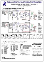
- The simplistic Salas low voltage shunt regulator