post2928.
Did the simulator indicate any difference in regulator performance when the cable inductances were added/subtracted? .
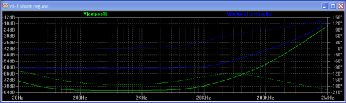
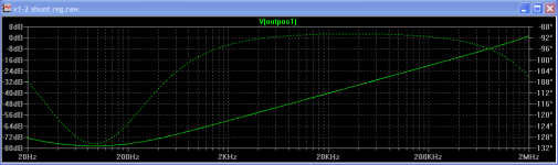
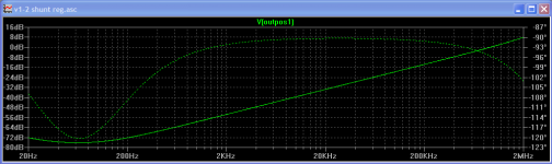
See attached. First is without inductors, second is with 6nH = 1cm of wire inductors, third is with 85nH = 3inches of wire, 4th is with 172nH = 6 inches of wire.
In the second graph I measured between +ve and the zero volt location you suggest.post2928.
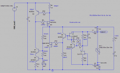
I see you have +ve out and -ve out in the two diagrams.
You have omitted Zero Volts out in both diagrams.
The zero Volts is NOT at the ground symbol.
The junction of L12 to L13 is outposZeroVolts.
Ken
Attachments
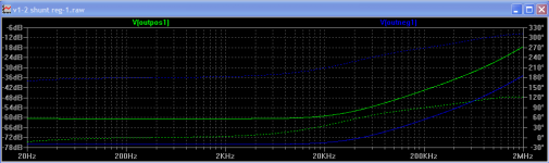
I think there are a lot of different messages in those 4 simulations.
I would to learn how to read those messages.
In the second, it is clear (I think) that the added inductance due to 10mm connections is adding a bit of phase change. Moving the Zero Volt tapping point brings the phase nearly back to where it was when connections were 0mm long.
I think the lessons here are threefold.
1.) longer wires changes the phase more.
2.) simulating with some real world estimates gives a different result from assuming every item is theoretically perfect.
3.) that the ground point must be modeled just as accurately as the +ve supply point.
4.) conjecture, not a lesson: Are the increased phase changes an indication that the longer wires are more susceptible to misbehaving due to component types and values and layout?
What other messages are in there? I suspect there are dozens.
Thank you Merlin
I will follow Salas advise.
I am not sure these resistors are ok for my actual builds 🙂
No problem, Salas give you a very good advice I will do the same in your case.
Klewis, you might try coupling the inductors, as would be the case with parallel wires. You can do this using by placing a statement on the schematic: "K1 L1 L2 .999"
K1 denotes the couple, so you could have two separate couples "K1" and "K2"
Then come the inductors being coupled (any number).
.999 is the coupling factor. I don't know about this, best to ask on the yahoo group for more info.
One the command is set, the inductor symbols will show a phase dot.
- keantoken
Keantoken,Klewis, you might try coupling the inductors, as would be the case with parallel wires. You can do this using by placing a statement on the schematic: "K1 L1 L2 .999"
K1 denotes the couple, so you could have two separate couples "K1" and "K2"
Then come the inductors being coupled (any number).
.999 is the coupling factor. I don't know about this, best to ask on the yahoo group for more info.
One the command is set, the inductor symbols will show a phase dot.
- keantoken
What is this meant to do?
Also, Ikoflexer generates plots of the impedance for the circuit, with the outputvolts / 1A (or something like that). What is the formula I want?
Ken
Did you make the V1.0 RS you were laying out once BTW? You would need a text line .params prb=0 and to give 1 on your Vsource and Isource AC amplitude, then run man and probe output. If you click on Vn you can edit it /1A and choose linear over y axis by hovering the mouse and left click there. You can set your Ohm scale limits there too.
Impedance of the output is calculated by measuring the effective resistance of the regulator with frequency. IE, if when drawing a 1A load, the output voltage sinks by .01V, your reg has an impedance of .01ohms as per Ohm's Law. The way I simulate this is to use a current source at the output set to idle load current (say 100mA or whatever you expect from the real load) and use it as the AC analysis source. LTSpice will then give a plot assuming theoretical 1A AC current draw, and clicking on the output node will give you the AC voltage change in volts. This effectively tells you the output impedance in ohms (volts change/1A current=ohms impedance). leftclick on the left scale and select "logarithmic" to see values in units instead of decibels.
Your inductors as they are are only arbitrary. There are no interacting magnetic fields, as there would be in real life. For example two wires next to each other will have inductive coupling along with their separate parasitic inductances. The commands I described allow you to add this coupling to the simulation.
- keantoken
Did you make the V1.0 RS you were laying out once BTW? You would need a text line .params prb=0 and to give 1 on your Vsource and Isource AC amplitude, then run man and probe output. If you click on Vn you can edit it /1A and choose linear over y axis by hovering the mouse and left click there. You can set your Ohm scale limits there too.
Salas,
You have a good memory! I didn't build it, got distracted, but have been following the thread all this time. Now, I'm more comfortable with v1.2 and will give it a go over the next month or two. I have two applications I want to try it with, a current feedback preamp and the VAS of an Allison power amp that Keantoken has helped with. Both are currently running but need proper chasis. So, I thought why not include these shunts in their final packaging (even though we know, in DIY nothing is ever final).
Regards,
Ken
Good plan. Your positive side CCS Mosfet is faster (less Ciss) than your negative side CCS one? Wouldn't it be better to equalize that between polarities, or the plus side is more critical in your applications? Also if there will be enough cabling carrying DCin to the regs, decouple with a 0.1u 5mm PP at their inputs to ground.
Good plan. Your positive side CCS Mosfet is faster (less Ciss) than your negative side CCS one? Wouldn't it be better to equalize that between polarities, or the plus side is more critical in your applications? Also if there will be enough cabling carrying DCin to the regs, decouple with a 0.1u 5mm PP at their inputs to ground.
Salas,
I plan to use the same mosfets in both the plus and minus versio, with the correct p or n type. My sims are different due to trying to find models that were stable and from a reliable source ; also wanted to try the Fairchild equals of the Irf240.
Ken
Salas,
I plan to use the same mosfets in both the plus and minus versio, with the correct p or n type. My sims are different due to trying to find models that were stable and from a reliable source ; also wanted to try the Fairchild equals of the Irf240.
Ken
Don't know beyond the few types tested, I hope they will work too. Let us know so we can have options.
Also if there will be enough cabling carrying DCin to the regs, decouple with a 0.1u 5mm PP at their inputs to ground.
Salas,
Is this correct?
Ken
Attachments


I went through the simulation and recorded the Watts at each device. This is for 75v in, approx. 60v out 120mA peak load (100mA base, 20mA excursions). I don't show the value for several of the devices if it's in the low pW range. The only thing surprising to me was the load at my R3 (R1 in Salas version). Does this look right?
Regards,
Ken
Regards,
Ken
Attachments
3W for the CCS and 6W for the shunt Mosfet when set at 200mA and connected to a 100mA load are the numbers you look for in your case.
Good plan. Your positive side CCS Mosfet is faster (less Ciss) than your negative side CCS one? Wouldn't it be better to equalize that between polarities, or the plus side is more critical in your applications? Also if there will be enough cabling carrying DCin to the regs, decouple with a 0.1u 5mm PP at their inputs to ground.
Salas,
Why did you use IRFP9610 on your medium voltage v1.2? You labeled it "Meaner". Was it due to higher voltage in and out or faster for you M/C pre amp, or none of the above?
Thanks
Ken
Due to I use it for even 2 MC channels (6 stages in total) with no or minor local decoupling and lousy PSRR in 4 of them, with common Tx and filter caps, I take advantage of 9610's even less coupling beyond audio range due to its very little Ciss and Crss. Its not as reliable for strong dissipation or hit transfer, nor has the mounting practicallity of a TO-247 which I generally prefer for easier stability in looser layout, especially in big currents and monoblock regs.
Hello Salas,
I was reading you post about shunt regulator, simplistic salas low voltage shunt reg.
I want to built this reg, reading the mega post, i got a doubt. I want a 5V 3A to feed a SqueezeBox.
In post #2548 you said, if i want a constant 3A i need to change some parts, witch parts?
I'm planning to use IRFP9140.
Another question, can i use a Capacitance multiplier with TIP147 in the input of this reg?
tks
What is the minimum current demand of the SqueezeBox?
What is the maximum current demand of the SqueezeBox?
What is the maximum current demand of the SqueezeBox?
- Status
- Not open for further replies.
- Home
- Amplifiers
- Power Supplies
- The simplistic Salas low voltage shunt regulator