Hi to all,
i would like to open this new thread, to discuss and list all pros. and conts. from Salas low voltage shunt regulator schematics to normal low voltage regulators, like the LM1085 or LT317.
I could imagine there are many members out there, who are not able to read these facts "between the lines" in the specific threads.
You are kidding. It is a night and day difference. I built many times the LM317/337/LT1085, etc for over two years. The Salas shunt reg killed them all.
My experience with the simplistic Salas regulator was outstanding. Before it I tried the usual three legged wonders, then built the Sulzer, Jung SR, and others. They seemed to add something unwanted to the sound. The simplistic Salas regulator just sounded right. It's so simple and cheap that there's no point in not trying it and seeing what it does for yourself. IMHO it is the best value of all regulators that I know of.
My experience with the simplistic Salas regulator was outstanding. Before it I tried the usual three legged wonders, then built the Sulzer, Jung SR, and others. They seemed to add something unwanted to the sound. The simplistic Salas regulator just sounded right. It's so simple and cheap that there's no point in not trying it and seeing what it does for yourself. IMHO it is the best value of all regulators that I know of.
Could you shortly explain the differences between salas latest circuit and yours?
Attachments
Could you shortly explain the differences between salas latest circuit and yours?
Hi!
I think design is very very simple! The sound is the best, There are alot of transitor is not good!
I so shunt regulator is the sample One or many Hight Cap!
thank!
I don't know what you mean, it's pretty obvious, no? There are similarities because I started with his simplistic and modified it, but there are technical differences as well. I've been using his simplistic until recently. I haven't built his latest yet, been too busy with my project.
I don't know what you mean, it's pretty obvious, no? There are similarities because I started with his simplistic and modified it, but there are technical differences as well. I've been using his simplistic until recently. I haven't built his latest yet, been too busy with my project.
Hi!
I want to say is: design application Author, less components, the influence of the components will be less. Because it will sound better! I think so
Now, What do you think about it??!
Thank!
quanghao, I'm trying to understand what you're saying. Are you saying that the Salas circuit has fewer components and therefore it will sound better?
quanghao, I'm trying to understand what you're saying. Are you saying that the Salas circuit has fewer components and therefore it will sound better?
Yes! I try to do in simplistic Salas Hight voltage Use 2 BC560.
But in the new design change 2 Bc560 by one 2sK170.*
I show, the new design is beter than it!
There are similarities because I started with his simplistic and modified it, but there are technical differences as well.
That´s the point, whitch i am interested in. 🙂
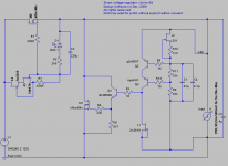
Different CCS implementation, different gain for the shunt portion, one using n-channel mosfets, the other using p-channel mosfets, you can see the differences yourself. I'm confused by your question, because the technical differences are very obvious, and we've talked about them in the respective threads. Lots of info there. Hope this helps.
So if i understand it right, i could use your latest 5d schematic for i.e. Input 9-20V and regulate it to 5-15V, right? 🙄
Is a load current of 2A max. to much for the circuit?
I am asking, because i´m thinking to upgrade all the regulators in my DAC.
Is a load current of 2A max. to much for the circuit?
I am asking, because i´m thinking to upgrade all the regulators in my DAC.
So if i understand it right, i could use your latest 5d schematic for i.e. Input 9-20V and regulate it to 5-15V, right? 🙄
Right. Keep in mind that for 5V output you need to use a logic level mosfet. See the thread, somewhere in the last few pages, where stormsonic has done that and shared his experience.
Is a load current of 2A max. to much for the circuit?
It's all about dissipating that heat. Think large heat sinks! I've had it up to around 3-4A at 20V, for a short time, even with a large heat sink. The circuit can do it. Remember this is a shunt design, meaning that if you need to have 2A available to the load, you will need to continuously draw a bit more than 2A. It make a nice heater 🙂
In my experience, the lm317 has horrible sound. It completely ruined my phono stage. Going to build the shunt reg next.
I would be interested in a brief explanation of how the circuit works as well.
I would be interested in a brief explanation of how the circuit works as well.
You see in the attachment picture, the regulators i would like to tweak.
Therefore i must design a PCB witch sit on top of the existing PCB.
At the moment i have made a sample layout with only one shunt regulator. Perhaps you could have a look on it.
Don´t worry about it, i don´t want to make a additional GB! 🙂
Therefore i must design a PCB witch sit on top of the existing PCB.
At the moment i have made a sample layout with only one shunt regulator. Perhaps you could have a look on it.
Don´t worry about it, i don´t want to make a additional GB! 🙂
An externally hosted image should be here but it was not working when we last tested it.
Attachments

dvb, my only comment is actually a request, that you please write on it that the layout is your design. I just wouldn't want people to chase me if they will build it like this. Hope you don't mind.
Otherwise, what can I say, my preference for this circuit would be for a different kind of layout. I'd make all tracks that carry high current at possibly high frequency thick, short, as straight as possible, and with no sharp edges. If I may suggest the Salas v1 or v1.1, there are a few layouts already made that should work well.
In any case, good luck with the board. Do come over to the appropriate thread once you start playing with the circuit.
I am looking for a shunt alternative to IC based regs that will get me down to 1.2v without using only half of a bipolar regulator. I am using a mix of the twisted pear shunts, LCDPS, some + and - versions of peranders's version of the JSR (SSR01/02) for voltages between +/-15v>+/-3.3v, but i'm stuck on the 1.2's I need for a sabre dac build. (ackodac) acko has some in developement that i'm sure will do nicely, but I would like alternatives and with these being fairly low cost, I would likely build these up in addition, see which works out best and utilize the other for another project or gift.
any suggestions? is this possible with the salas or modified salas with a change of reference?
any suggestions? is this possible with the salas or modified salas with a change of reference?
Have a look at this one, also by salas and disco
http://www.diyaudio.com/forums/powe...-voltage-shunt-regulator-162.html#post2014178
http://www.diyaudio.com/forums/powe...-voltage-shunt-regulator-162.html#post2014178
- Status
- Not open for further replies.
- Home
- Amplifiers
- Power Supplies
- The simplistic Salas low voltage shunt regulator vs. LD1085/LM317