Can someone please recommend power supply schematics for my first DAC? I want it to be as simple as possible, but without serious flaws. It's going to be DIR9001 + PCM1794A, so I need +3.3V, +5V digital and +5V analog lines.
I was going to order a transformer with separate coils for each output line (plus 2x~17V for I/U), but it seems that at the moment it would cost too much so I might have to go with a simple 2 x 17V transformer, powering everything with it. So it'd be nice if the power supply can feed from a single coil and still retain decently clean output.
I was going to order a transformer with separate coils for each output line (plus 2x~17V for I/U), but it seems that at the moment it would cost too much so I might have to go with a simple 2 x 17V transformer, powering everything with it. So it'd be nice if the power supply can feed from a single coil and still retain decently clean output.
Last edited:
It would be more usual to go with a "master" regulator at around 7 volts, then use local
regulation for each of the ICs individual voltage requirements. A 9 volt transformer at around 500mA would be good here.
You would use a separate transformer and regulator for I/V or buffers that require
a dual rail power supply. A transformer with two 15 VAC secondaries at around 500mA
would be good here.
Of course, this is just a rough suggestion, your needs may be different.
Thanks. How important is it to have 2 separate transformers for ICs and I/U, as opposed to a single transformer with 3 output coils?
The coils for the digital side could interact and transmit noise to the analog
side if they are sharing the same primary coil.
side if they are sharing the same primary coil.
That much is clear to me. I didn't know, though, if this effect is significant enough to take into account. Since you've stressed it - I assume it might be, thanks.
Is my understanding correct that you've advised the double stage voltage conversion for simplicity, i. e. generally one would want distinct circuits, but this simpler design may still have reasonable performance? If so, how simple can the second stage be? Can it be a mere Zener diode, considering that the current is very small?
To be honest, the reason I've specifically asked for schematics is because I have very little understanding of both modern power supply design and the specifics of the audio DAC application. For instance, I could find and use some voltage regulator IC and get the required output voltage, but I wouldn't know where to put capacitors, which type and capacity they should have etc. I also don't know which regulator ICs are better suited for this application (I've only built non-stabilized power supplies so far).
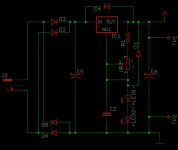
Here is an example of a more modern implementation of a LM317 regulator.
The two LEDs set the output voltage and the VR adjusts the current through
the LEDs to trim the output voltage.
If we assume the LEDs drop about 2 volts each, the output voltage
should be 5.25 volts. You could build this with three 2 volt LEDs or
you could use a 6 volt zener in their place. Another option would
be a 5 volt zener with a 1N4148 in series to provide better temperature
tracking. All of these options would provide about 7 volts out.
For local regulators, you can use the popular LM2985 regulator for
the needs of each IC.
The same principal in the example schematic can be used to build a dual
rail power supply as well. A 13 volt zener with a 1N4148 in series will
result in about 15 volts out.
Attachments
Thanks! I actually do have a schematic for the dual rail +/-15V supply specifically recommended for the I/U I'm going to build, so the DIR9001 / PCM1794 supply is my only problem right now.
Is there any reason why I can't / shouldn't just use a bunch of LP2985 without LM317? Is it because they can't suppress ripple?
If you want/have to power everything from a same winding, it is a good idea to provide some isolation in between the pre-regulator stage and the local regulators with LC filters.
The lm317 is useful because it limits the power dissipation in the local ldo regs and make it constant, even if your mains voltage fluctuate.
The lm317 is useful because it limits the power dissipation in the local ldo regs and make it constant, even if your mains voltage fluctuate.
Makes sense. Can you give me an idea of the filter schematics? Or at lest structure and cutoff frequency?
The coils for the digital side could interact and transmit noise to the analog
side if they are sharing the same primary coil.
If you worry about that, you should also worry about the noise being transmitted through a common power connection even if you have separate transformers (the primaries of both transformers are directly connected to each other through the power connection after all). To be really sure of no interaction, I guess you should get a power feeds from two different utilities... 🙂
If you worry about that, you should also worry about the noise being transmitted through a common power connection even if you have separate transformers (the primaries of both transformers are directly connected to each other through the power connection after all). To be really sure of no interaction, I guess you should get a power feeds from two different utilities... 🙂
I was thinking two different sets of solar panels...😉
I was thinking two different sets of solar panels...😉
As long as they are not parallel - too much mutual capacitance 🙂
I have a couple specific questions, as a guy with no experience to guys with some experience:
1. Can I hear the difference in sound if I separate DIR9001 and PCM1794 power supply?
2. Can I hear the difference in sound if I separate 1794's digital and analog supplies?
3. Can I hear the difference in sound if I separate the two DIR9001's supplies (I believe one is dedicated to PLL and output, and the other for the rest)?
Remember, I'm not talking about a high-end design with PCB, SMD components and high-quality brand resistors and capacitors. But I do want to achieve the best possible with the components available to me. I hope to outperform EMU0404, and I know it's going to be tough at best.
I have a couple specific questions, as a guy with no experience to guys with some experience:
1. Can I hear the difference in sound if I separate DIR9001 and PCM1794 power supply?
2. Can I hear the difference in sound if I separate 1794's digital and analog supplies?
3. Can I hear the difference in sound if I separate the two DIR9001's supplies (I believe one is dedicated to PLL and output, and the other for the rest)?
Remember, I'm not talking about a high-end design with PCB, SMD components and high-quality brand resistors and capacitors. But I do want to achieve the best possible with the components available to me. I hope to outperform EMU0404, and I know it's going to be tough at best.
The only one who can tell if you can hear a difference is you - and only by listening (and with your ears, not your eyes).
Indeed, bad wording. I should have asked if it is humanly possible to hear the difference.
What I'm trying to ask is what I should bother with and what I shouldn't bother with. I want to keep the design as simple as possible, but I also don't want to kill performance by not implementing something that's not very hard to do. If it's not going to sound better than EMU then it would all have been in vain.
What I'm trying to ask is what I should bother with and what I shouldn't bother with. I want to keep the design as simple as possible, but I also don't want to kill performance by not implementing something that's not very hard to do. If it's not going to sound better than EMU then it would all have been in vain.
Last edited:
Indeed, bad wording. I should have asked if it is humanly possible to hear the difference.
We are still very much in a grey area. There are a lot of things where we can measure a difference, and where people claim they can hear a difference, but where there hasn't been any proper, controlled blind listening tests verifying people can *actually* hear the difference.
What I'm trying to ask is what I should bother with and what I shouldn't bother with. I want to keep the design as simple as possible, but I also don't want to kill performance by not implementing something that's not very hard to do. If it's not going to sound better than EMU then it would all have been in vain.
It will be hard to beat a properly designed, well implemented design that has been done using smd components on a proper professionally designed PCB.
My personal view is that while it might be possible to measure some differences from those power supply options, I think they will be dwarfed by the analog and circuit layout issues.
If you are looking to get the most out of the PCM1794a, I would use the Wolfson WM8804 rather than the DIR9001.
Thanks for the advice, I'll try to get WM8804. I already have a bunch of DIR9001s, so will probably have to start with those.
I would use four local regulators...two for the DIR9001/WM8804 and two for the PCM1794a.
That should give you good performance without going overboard.
Personally, I would go with the 317 based pre-regulator, but there is nothing with 00940's
suggestion either, if well executed.
That should give you good performance without going overboard.
Personally, I would go with the 317 based pre-regulator, but there is nothing with 00940's
suggestion either, if well executed.
- Status
- Not open for further replies.
- Home
- Source & Line
- Digital Source
- The simplest DAC power supply source design without glaring flaws?