I install vcad on notebook today
There is list must fill on the driver
D1 SPL ? Z ?
D2 SPL ? Z ?
There is list must fill on the xover
I choose active linkwitz then
fo ? Min ? Max ?
Qo ? Min ? Max ?
fp ? Min ? Max ?
Qp ? Min ? Max ?
So where do i start ? Really blind
I will look about this virtuixcad too
There is list must fill on the driver
D1 SPL ? Z ?
D2 SPL ? Z ?
There is list must fill on the xover
I choose active linkwitz then
fo ? Min ? Max ?
Qo ? Min ? Max ?
fp ? Min ? Max ?
Qp ? Min ? Max ?
So where do i start ? Really blind
I will look about this virtuixcad too
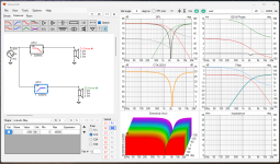
VituixCad does have the electro mechanical parameters for you Scan Speak driver have a look in the Tools Tab and enclosure. See attachment 3. for some info
I have attached some screen shots for a active second order LR crossover, A passive one using Markbakk values. Please note the VituixCad simulation is using a flat 8 ohm impedance and your driver is specified as a 4 ohms device, The information should allow you to do the same and get a better feel for crossover related things.
I f you were in fact using an 8 ohm driver possibly the inductor value would be approx twice the value and the parallel capacitor half its value,
A very big point here, you can design an crossover this way that should handle the Xover transition very nicely. But as we are dealing with simple flat lines that in no way represent the real response of the drivers there will be diffraction effects from the cabinet shape to be considered, predominantly baffle step affecting the woofer response which is likely to mean a bigger inductor is needed to bring the midrange back down to align with the real world room bass response which will be lower by 6 - 9 dB than this simulation. If the speaker is used close to a wall or in a corner of a room you will have a bass boost (Room Gain) and may not need as much correction. However, if you were designing for a speaker to be used well into the room you may need the full 9dBs or thereabouts.
These cabinet diffraction effects will also effect the tweeter response, but maybe those aspects are a bit further along the learning curve for now.
There is a mistake in the frequency response shown can you spot it?
Good luck.
Attachments

Hi Markbakk
Are that data on virtuixcad need to measure on our driver ?
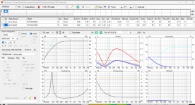
This is what a real acoustic response (14 cm unit) in an enclosure looks like. You don't only have to establish the crossover, you also have to compensate for the nonlinear behaviour of the driver in the enclosure. As you can see, the variation even in the range >100Hz is quite big. So to be honest, yes, you need raw driver + enclosure acoustic measurements and impedance measurements, because those don't look like the impedance of a resistor either:
The shorts: you can't use any calculator or simulation app like VCad with good results unless you acquire measurement data. Tracing the data sheet and importing that into VCad is a humble beginning, but again to be honest, I'd skip that and get some cheap measurement gear like this (or get the components and compose yourself).
Compare it to driving a car. You don't, really don't know how fast you are driving until you have a speedometer (and you have a look at it). Measuring is knowing.

Thank you raymondj for simulation & crossover design
Thank you makbakk to let me know the benefit. I will learn how to do this
For this project i bought box from china because im not a carpenter. As you know people promise u everything but give nothing, i was little bit disapointed made speaker box before.
Thank you makbakk to let me know the benefit. I will learn how to do this
For this project i bought box from china because im not a carpenter. As you know people promise u everything but give nothing, i was little bit disapointed made speaker box before.
Did you spot my mistake with the phase?
If you have VituixCad up and running and have copied the crossover, with the mouse hover over either driver , and right click and in the new drop down menu select invert. Now what does the response look like? in the SPSL and GD and phase graphs?
If you have VituixCad up and running and have copied the crossover, with the mouse hover over either driver , and right click and in the new drop down menu select invert. Now what does the response look like? in the SPSL and GD and phase graphs?
Yes, you understood the point.
The phase reversal is used a lot with second order overs. It doesn't matter where it is applied either tweeter or Woofer. Simply the fact that they are wired 180 degrees out of phase to each other. There is another subtlety here, you will not get the nice flat response, only when care an attention has been paid to mount the drivers such that their acoustic centres are time aligned. You can play with the physical position in VituixCad and see what happens as you move the tweeter forward or backwards in the Z plane for the driver.
When do you cabinets arrive from China and what tweeter are they configured for your Dynaco?
Yes, That the best way.
Simply because it is real data obtained with the driver in the cabinet, with all the diffraction effects. Best not to rely on just the main axis. Ideally take measurements at 30,45,and 60 degrees to let you understand what really happens.. I do not know how cheaply you can do it for off the top of my head, to obtain good measurements needs reasonable equipment.
A lot of people use a two channel beginners recording option, from Behringer or Focus rite and a Dayton microphone that needs energising via the phantom power from the recording device.
Hopefully somebody else will jump in and make suggestion. I imagine there are some Chinese sourced or possibly local alternatives you could try
This interface and this microphone plus some cables and clips, a stand and a few resistors will do the job for reliable measurements of SPL response and impedance. You need a computer too and a download of REW. Plus: quite some time to get acquainted with the stuff.
- Home
- Loudspeakers
- Multi-Way
- The Simple Speaker ... need help