Hi everybody,
I need some help to build diy speaker
My first question is if you have a diagram like this,
what frequency you will cut it for twitter-woofer?
And what the reason?
Curve is look the same and a question from me
Is that ok to cut it freq between 5500 - 6000 hz?


Just say thank you for your help before
I need some help to build diy speaker
My first question is if you have a diagram like this,
what frequency you will cut it for twitter-woofer?
And what the reason?
Curve is look the same and a question from me
Is that ok to cut it freq between 5500 - 6000 hz?
Just say thank you for your help before
An old rule of thumb for a tweeter is a minimum of 2 x Fs, if you are not sure 3 x Fs should help with power handling and usually crossing higher with a good quality tweeter will keep distortion low. You can play with this depending on how loud you want to listen 3 x Fs should be safe for most tweeter if you want to use them at higher volumes.
Your first graph which i assume is a a tweeter, with B and K plotting scale min 60 dBs suggest you have a 90 dB tweeter with a resonance at at lets call it 1.5KHz therefore start around 3Khz second order.
The lower graph for maybe a 125mm driver start diverging at 1.5KHz from the separation of the response traces 0, 30 and 60 degrees so maybe between 2 -2.5KHz second order Being "Picky", maybe a notch at 5Khz depending on how that resonance couples into the overall design, often not needed even if you can see its effect in modelling software.
Which could mean a bit of a response droop between the woofer and tweeter? Usually by component selection and modelling the driver spacing you can fill this in as required, maybe come a bit lower on the tweeter might be an easy component change?
The woofer midrange sensitivity is 85 dB or so don't forget you will loose between 6-9dB in the bass region dues to Baffle step and diffraction loss. Which also means you will probably need some attenuation on your tweeter.
Re your question at a crossover at 5500 -6000 it will work, but 2-3K should give you a better overall response, I think.
As the resonance is not clearly defined to me, you may have to use a impedance compensation circuit to flatten that low frequency rise.
Good luck, if you tell us what the drivers are then maybe you will get some practical advice from people who have used them.
Last edited:

Hi Raymondj, thank you for advice
Tweeter is dyn t330d with fs 750 hz
So if 3 x 750hz, it will cut in 2250 hz

Woofer is ss 15w/4531

Tweeter is dyn t330d with fs 750 hz
So if 3 x 750hz, it will cut in 2250 hz
Woofer is ss 15w/4531
The data sheet for the tweeter suggest minimum frequency of 2KHz and impedance correction parallel between terminals of 1.5uF and 8.2 ohms.
Hopefully it will sound wonderful. You have used this tweeter before, a long time ago ?
Hopefully it will sound wonderful. You have used this tweeter before, a long time ago ?
As i didnt have speaker program i used free speaker program from vh audio really thanks for this https://v-cap.com/speaker-crossover-calculator.php

Hi raymondj
I used on speaker "fail" project maybe 10 years ago and i heared the sound was beautiful. I hear on a view friend speakers too, who install their esotar & esotar2 on the car audio
I used on speaker "fail" project maybe 10 years ago and i heared the sound was beautiful. I hear on a view friend speakers too, who install their esotar & esotar2 on the car audio
Last edited:
After 2khz - 3khz and trial with free program so we got focus on cutting frequency .. how do you think all my brother in diyaudio forum
Btw raymondj why you can tell that
min freq is 2khz ? Can u tell me ?
I dont see 2khz number in the spec
Looks like there is another question after we answer one question on speaker build


Btw raymondj why you can tell that
min freq is 2khz ? Can u tell me ?
I dont see 2khz number in the spec
Looks like there is another question after we answer one question on speaker build
Good day Pocoyo,
There is a lot of things here that need considering.
I do not know if you have become tired of the original design that you used, the great thing about speaker building is that you should always have sound.
To answer your question I put your tweeter into google or some such and did a search for your tweeter data sheet. I am not familiar with it personally, but believe it had a good reputation and was expensive for the time. Unless specified by the manufacturer I would stay away from the idea of using it first order unless you never stray over the mid 90 dB sound levels.
Fortunately for me, the well known speaker designer Troels Gravesen has used you well respected Scan Speak woofer. Plus lots of other designers over the years. I am not sure if your original design was chasing some kind of Sonus Faber speaker of the time. Anyway, please have a look here
http://www.troelsgravesen.dk/Revelator-51.htm
Mid way through his webpage for the design he produces some response graphs, which show the baffle step aspect for the bass, have a look and you will see there is a rise in the red coloured woofer response somewhere around the 450-500 Hz mark. This highlights the fact that a simple crossover component designer will not provide an optimum solution, even if you use the the loudspeaker impedance taken from the data sheet.
Is there a possibility that you could buy a reasonable microphone and two channel sound card to allow you to take accurate measurements using Rew or Arta? Then you could import the real data into speaker crossover design software like Xsim, or speaker design software like VituixCad. Have a look at the VituixCad help file for more understanding. See here for the beginnings.
https://kimmosaunisto.net/
This should allow a good to excellent design depending on how much effort you put into this I would strongly recommend getting to grips with VituixCad, it is not the easiest to use straight out of the box, and some reading of Loudspeaker design books, Cook Books will prove extremely useful if you haven't spent much time with them.
If I can find the tweeter data sheet again I will send you a link.
Didn’t the OP post it already?If I can find the tweeter data sheet again I will send you a link.
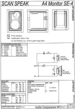
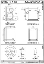
Consider a simple but good design as a starting point, the A4 monitor SE from Ralph Smulders. Tweeter is different, but not thát different.
Attachments
Last edited:
Hi Markbakk,
Yes you are right, Pocoyo did publish the specs, I was referring to the manufacturers data sheet that I looked for.
https://hifi-wiki.com/images/e/e3/DYNAUDIO_T330D_ESOTAR-001.jpg
and
https://hifi-wiki.com/index.php/File:DYNAUDIO_T330D_ESOTAR-002.jpg
Yes you are right, Pocoyo did publish the specs, I was referring to the manufacturers data sheet that I looked for.
https://hifi-wiki.com/images/e/e3/DYNAUDIO_T330D_ESOTAR-001.jpg
and
https://hifi-wiki.com/index.php/File:DYNAUDIO_T330D_ESOTAR-002.jpg
Hi Raymondj
If the woofer must push on low freq maybe better we cut the freq on the 2khz
As 15w 4531 only 87 db so it will be better if we change 1st to 2nd order
There is 3 ways for 2nd order what is different between one and another
1 Linkwitz-Riley
2 Butterworth
3 Bessel
If the woofer must push on low freq maybe better we cut the freq on the 2khz
As 15w 4531 only 87 db so it will be better if we change 1st to 2nd order
There is 3 ways for 2nd order what is different between one and another
1 Linkwitz-Riley
2 Butterworth
3 Bessel
Hi Markbakk thank you for posting
If the ss d2905 4ohm just a little bit
different with the dyn tweeter 8ohm
If the ss d2905 4ohm just a little bit
different with the dyn tweeter 8ohm
Well, I suspect the Dynaudio to be a little bit brighter, but otherwise the crossover of the system I posted might work out just fine. Of course better is the enemy of good, but you need to get your system measured (acoustic response and impedance) to obtain better results than with that crossover. And since the cost of these parts won’t break the bank, I’d give it a try.
Pocoyo,
Regarding your second order filter question a thorough answer would take quite some effort to do it justice, and I would be the wrong person to do it.
Due to electrical component choices regarding the different crossover types, the values for the inductors and capacitors for each of the crossover types will be different. They will also differ in terms of how they sum at the Xover frequency, their phase and slope and group delay.
I think Butterworth first saw the light of day in the 1930's they are characterised by an amplitude bump at the crossover frequency. They were popular in the 60s and 70s in many UK designs.
Bessel was a mathematician from the 18th Century, and his maths/filter design has a flat group delay in the passband, and these filters are used when a designer want to exploit this characteristic., possibly to get the best impulse response.
Linkwitz-Riley are the relative newest type of filter design in the group.
They are named named after to of the modern day speaker and electronics greats, the slope is different as it is made up from the equivalent components you would obtain if you cascaded Butterworth filter components, also the tweeter should be wired out of phase. The main advantage is a somewhat different filter knee shape which gives a flat frequency response at the crossover frequency. Ideally they work well very well when the drivers are closely time aligned on a sloping or stepped baffle.
https://en.wikipedia.org/wiki/Linkwitz–Riley_filter
I suggest further reading or more internet research on this topic, you will soon find some graphs that explain the shapes and other characteristics.
With modern software tools it is reasonably easy to start with a target filter slope, but by the software, or manually iteratively adjusting components values so as to obtain a target frequency / power response .
This in fact means that quite often the design is close to exhibiting one of the second order responses but it may not actually match exactly the target slope. There are lots of compromises in speaker design.
Generate FRD and ZMA files for your drivers using a graph tracing tool as per the YouTube video and import them in VituixCad and start playing with the Crossover components using the Troels Gravesen schematic or Markbakk's design that he posted. the fact that there are no component values, simply the topology makes it even more fun as you can play with values to your hearts content.
I still believe if there is a few of you it would be worth sharing the cost and investing in some kind of measuring system and use each others strength and knowledge to work you way to a better understanding of the whole design process and become familiar with VituixCad, you don't have to buy it for non commercial use, but you can make donations as you wish.
While it is a start, I wouldn’t bother these days. Get a cheap measuring mike, a second hand usb audio interface and measure yourself. Tracing never and never gives you confirmation on the end result. You’ll miss any reference.Generate FRD and ZMA files for your drivers using a graph tracing tool
The component values of the design I referred to are given by the way. Just copy enclosure and crossover and tweak high output with resistor in tweeter path.
Good day friends
I read some web about 2nd order type
Looks like i need a lot of reading bout this. Is there any video / youtube 🤣🤣
Just kidding ..
On my temporary conclusion it will go to 2nd order with linkwitz riley
Raymonj i try to download vituixcad but i cant open it now or need to donate first?
I read some web about 2nd order type
Looks like i need a lot of reading bout this. Is there any video / youtube 🤣🤣
Just kidding ..
- look from google
- Look from troel & humble made hifi
- look from diyaudio
Butterworth, Bessel, Linkwitz-Riley... What's the difference, & what's your favorite?
Hi all!
After the "what's your favorite crossover slope?", here's the "what's your favorite crossover type?" 😉
I was just wondering, what's the difference between all of them (if you know others, feel free to introduce them!), in terms of results/caracteristics, but also in the maths.
At first, I thought that the difference between them was the Q of the filter. But after reading some articles and threads, I have some doubts. Is this true?
Alex
On my temporary conclusion it will go to 2nd order with linkwitz riley
Raymonj i try to download vituixcad but i cant open it now or need to donate first?
While it is a start, I wouldn’t bother these days. Get a cheap measuring mike, a second hand usb audio interface and measure yourself. Tracing never and never gives you confirmation on the end result. You’ll miss any reference.
The component values of the design I referred to are given by the way. Just copy enclosure and crossover and tweak high output with resistor in tweeter path.
Can i do it with notebook ?
Firstly my earlier explanation on filters was basically a quick snapshot and i could have worded some points better. I missed the time window to Edit things.
In the seventh paragraph this is what I was struggling to say.
"With modern software tools it is reasonably easy to start with a target filter slope, but then, by the use of crossover design software carrying out automatic optimisations, or by a user manually adjusting components values to make a nice frequency / power response the original Bessel/LR/Butterworth filter slope is no longer met.
This in fact means that quite often the design is close to one of the second order responses , but it may not actually match exactly the target slope. There are lots of compromises in speaker design."
-------------------------------------------------------
As to your latest question.
I cannot understand why you cannot download VituixCad to a PC with with a recent Windows operating system.
I have attached a snip of the operating requirements. So if you PC meets these requirements I would have another attempt to download the software.
Attachments

- Home
- Loudspeakers
- Multi-Way
- The Simple Speaker ... need help