Greetings, Friends. I wanted to share my progress on the little SE EL84 amp I've been playing with.

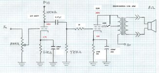
It's undergone a host of changes since my last update. I've installed a pair of 10w 3.5k OPTs, rewired the output tubes for Triode mode, and rewired the driver stage to mirror @Suncalc 's Marblewood Amp. In fact, I seem to have arrived at an EL84 version of that design. Per the EL84 datasheet, a pair of EL84 wired in triode with a 270ohm Kr will pull 2x 36mA = 72mA. Trying to be frugal as the PT only is rated for 104mA.

And the power supply

obligatory gut shot - Large Orange Caps!

As expected, the smaller OPTs deliver less bass than the 15W, but the amp has such a delightful clarity through the upper range that I don't miss it. I had an afternoon of Joe Pass records that really made me fall in love with the amp. Rewiring the driver stage to the "Universal 4S Preamp" made a huge improvement, thanks Matt for posting such wonderful designs!
It's undergone a host of changes since my last update. I've installed a pair of 10w 3.5k OPTs, rewired the output tubes for Triode mode, and rewired the driver stage to mirror @Suncalc 's Marblewood Amp. In fact, I seem to have arrived at an EL84 version of that design. Per the EL84 datasheet, a pair of EL84 wired in triode with a 270ohm Kr will pull 2x 36mA = 72mA. Trying to be frugal as the PT only is rated for 104mA.
And the power supply
obligatory gut shot - Large Orange Caps!
As expected, the smaller OPTs deliver less bass than the 15W, but the amp has such a delightful clarity through the upper range that I don't miss it. I had an afternoon of Joe Pass records that really made me fall in love with the amp. Rewiring the driver stage to the "Universal 4S Preamp" made a huge improvement, thanks Matt for posting such wonderful designs!
Attachments
Last edited:

Nice project and well executed. I know this sounds heretical but it might be worthwhile trying a little feedback on the secondary particularly if running in UL mode to get the output impedance. I've spent most the past 3 decades espousing the virtues of zero feedback SE amplifiers, and over the past year or two have run into a couple of situations where lower output impedance and a modest amount of feedback would have been beneficial. (I am driving compression drivers directly with my 300B SE 0 fdbk amps)
I keep telling myself I need to design a simple EL84 amplifier. My very first tube amp at the age of 16 was a salvaged Magnavox EL84 amp. (I converted it from 6EU8 to 12AX7A, and replaced the fried power transformer with a multi input voltage power transformer to run it on 220V. (In Brussels) I still have fond memories of that amplifier five decades later.
I keep telling myself I need to design a simple EL84 amplifier. My very first tube amp at the age of 16 was a salvaged Magnavox EL84 amp. (I converted it from 6EU8 to 12AX7A, and replaced the fried power transformer with a multi input voltage power transformer to run it on 220V. (In Brussels) I still have fond memories of that amplifier five decades later.
Volt Meter on eBay. It's wired between C1 and ground. Only hangup is, it's 45mm and my chassis punch is 44mm. A little filing with the 14" half-round gets it in.
As far as feedback, the chassis has 2 holes drilled in the back to allow for DPDT switches to sample different FB configurations. And K bypass configs, too. I'm not opposed to FB, as long as my dinky PT can keep up.
Thanks for taking a look,
Will
As far as feedback, the chassis has 2 holes drilled in the back to allow for DPDT switches to sample different FB configurations. And K bypass configs, too. I'm not opposed to FB, as long as my dinky PT can keep up.
Thanks for taking a look,
Will
Also, linking Pins 6 & 3 allows me to use 6p15p tubes. There's talk put there of using a 1uF 400v cap to link the two...thoughts?
Where is C1?Volt Meter on eBay. It's wired between C1 and ground. Only hangup is, it's 45mm and my chassis punch is 44mm. A little filing with the 14" half-round gets it in.
As far as feedback, the chassis has 2 holes drilled in the back to allow for DPDT switches to sample different FB configurations. And K bypass configs, too. I'm not opposed to FB, as long as my dinky PT can keep up.
Thanks for taking a look,
Will
The first cap, the reservoir capacitor. It's the point with the highest voltage in the circuit. This meter goes in between that point and ground.
The same company makes ammeters, which I assume go directly in line (series) between C1 and the choke to measure the total amp draw of the circuit. A voltage measurement could also be taken at the power tubes' cathodes, summed, and displsyed on a 0-25v meter. Any serious deviation would indicate a problem with a power tube.
w
- Home
- Amplifiers
- Tubes / Valves
- The Runt - A nice little SE EL84 amp.