Did you assume infinite output impedance of the first tube?
Of course not. Impedance is finite, and for this tube in this mode has a value of approximately 500 kom.
Ah, thanks! And which one is equivalent to those in your design?
Best regards!
I didn't have those tubes. The Handbook says they're identical. Probably the Soviet 6Zh1P is a clone of these tubes.
I think this is similar to a TRAFOMATIC phono stage that was reviewed at 6moons.
https://6moons.com/audioreviews/trafomatic11/schema1_big.png
https://6moons.com/audioreviews/trafomatic11/schema1_big.png
Yes, RIAA correction is very similar.
In the final version T15B capacitors in cathodes are excluded.
Of course, the gain was less. But much less was the low-frequency and ultra-low-frequency noise.
Probably the source of the noise was flicker noise capacitors.
In the final version T15B capacitors in cathodes are excluded.
Of course, the gain was less. But much less was the low-frequency and ultra-low-frequency noise.
Probably the source of the noise was flicker noise capacitors.
Last edited:
I should have been more specific.
No question your circuit looks like a step beyond!
Thanks for sharing it!
No question your circuit looks like a step beyond!
Thanks for sharing it!
I think this is similar to a TRAFOMATIC phono stage that was reviewed at 6moons.
https://6moons.com/audioreviews/trafomatic11/schema1_big.png
I believe this is not Trafomatic's circuit although they do manufacture it. The topology has been popular on various Russian sites for many years. My research at the time indicated the first incarnation belonged to Komissarov, but perhaps Zampotech knows better and will correct me.
My built used an EF86 and a 6N30P and i liked the simplicity. The regulated G2 is indeed a must. Gain was on the low side and distortion on the high: the concept of a variable anode load does not yield particularly low distortion. It sounded pretty good though.
Attached is Komissarov's circuit
Attachments
I would defer to you without protest!
The schematic I linked was part of a review in 6moons - and it was said this was not the exact circuit TRAFOMATIC used.
It does have an appealing look about it. I have never built it nor have I ever heard a phono amp using the topology.
I don't get out much ... !
The schematic I linked was part of a review in 6moons - and it was said this was not the exact circuit TRAFOMATIC used.
It does have an appealing look about it. I have never built it nor have I ever heard a phono amp using the topology.
I don't get out much ... !
This scheme is a continuation of the schematic of the phonopreamp T24 (2006)

Scheme Komisarova really popular on Russian websites.
The T15B scheme is more similar to the Komissarov scheme, though a different development path.
this method of correction has long been known. It was used in long-distance communication technology.
Scheme Komisarova really popular on Russian websites.
The T15B scheme is more similar to the Komissarov scheme, though a different development path.
this method of correction has long been known. It was used in long-distance communication technology.
Last edited:


Announcement for everyone.
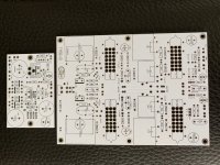
If you wish to repeat this preamp, you can order printed circuit boards from the links:
Phonopreamp T15B PCB-A - Share Project - PCBWay
Phonopreamp T15B PCB-B - Share Project - PCBWay
Phonopreamp T15B PCB-C - Share Project - PCBWay
PCB-A this is the input connector Board
PCB-B this is the amplifier Board
PCB-C this is the power supply Board
The developer has allowed to keep the links open until April 28. Then the possibility of ordering will be closed.
Board design will be provided upon request.
Sorry, I don't see any prices?
Best regards!
Until April 28, you pay only to the manufacturer of printed circuit boards.
This is what the basic KIT T15B looks like after assembly.


The KITs will be 115 volts and 220 volts.
The KITs will be 115 volts and 220 volts.
- Status
- Not open for further replies.
- Home
- Source & Line
- Analogue Source
- The RIAA phonopreamp T15B on miniature tubes. KIT