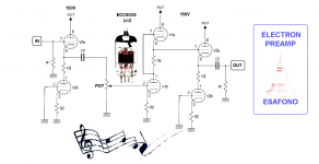
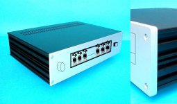
my last project is a SRPP tube preamplifier
with a special input and output buffer:
cathode follower with a current source 😕
that is to have a compensation of "triode tone mark"
in other word appear technically unnecessary but "magic for music"
with a special input and output buffer:
cathode follower with a current source 😕
that is to have a compensation of "triode tone mark"
in other word appear technically unnecessary but "magic for music"
Attachments
Last edited:
Hi,
I see a circuit with an input and an output cathode folllower, with a SRPP gain stage between.
I see no point in having either cathode follower, the input one is not needed to drive a pot and a SRPP input, and the output Z of the SRPP should be low enough to drive a cable without the extra CF.
Why add them? KISS is my key principle, and a CF (even with a CCS load) still is not 100% transparent.
Regards, Allen
I have to agree with Allen.. It seems needlessly complex which can't IMHO help the sound. Simpler is usually better.😀
Simpler is usually better
of course
but I think the success of the SRPP is just replacing the anode resistor load with a triode:
an active load is good for the cathode in terms of sound
it is true that the principle of character's compensation is not measurable
but your ear will notice a more realistic scene
just because works another identical unit in opposition of phase
a too modern concept for designers more orthodox🙄
I have no argument with your use of the SRPP topology as a gain stage, but cannot see why you need a CF buffer before it AND after it. Pointless IMO.
Regards, Allen
Regards, Allen
Input cathode follower: do not need. Ditch it.
Output CF: use a proper CCS tail load, either cascoded, discrete BJTs, a CCS IC, or if you insist on a "no sand" solution, a high g(m) pentode CCS. Triodes are horrible as CCSs.
Output CF: use a proper CCS tail load, either cascoded, discrete BJTs, a CCS IC, or if you insist on a "no sand" solution, a high g(m) pentode CCS. Triodes are horrible as CCSs.
Input cathode follower: do not need. Ditch it<<
Agreed.
>>Output CF: use a proper CCS tail load, either cascoded, discrete BJTs, a CCS IC, or if you insist on a "no sand" solution, a high g(m) pentode CCS. Triodes are horrible as CCSs.
Miles, why does he even need an output CF? A well designed SRPP's purpose is to act as a active load AND a "CF" with a low OPZ.
But if you want to do a really sonically transparent CF, I believe you need to use my SLCF, which can be seen as the last section of my FVP-5A schematic, linked here:
http://www.vacuumstate.com/index.tpl?rubrik=8&lang=2&a=%88%5BD%CDmc%B4%F7&b=734271.4389191557
Regards, Allen
I can't see how this thing can work . Look at the grid arrangement on the input stage V2A .
316A
316A
i agree the input cf could be ditched, however,it has been mentioned a few times that the srpp needs a well defined load. i believe the output cf provides a near constant low capacitance load that may actually lower overall distortion.
That circuit does not contain an SRPP- the middle stage is a current-source loaded triode, it is not push pull!
An SRPP does NOT contain a cathode follower, does not have a low output impedance, and is not suitable as a line driver. Even if the middle stage were converted to an SRPP (why bother?) the output impedance would be in excess of 4k.
A true cathode follower output (like he already has) is still necessary.
Last edited:
Miles, why does he even need an output CF? A well designed SRPP's purpose is to act as a active load AND a "CF" with a low OPZ.
The SRPP is balanced for three load conditions: a dead short (both VTs operate as grounded cathode amps -- not exactly useful though) an open or Hi-Z load (if the current has no additional path but through both tubes, balance is guaranteed) the one specific load impedance for which it was designed. This is not a problem when the SRPP is used for what it was originally intended: an active pull-up/active pull-down line driver that could be matched to the characteristic impedance of the T-line it was driving. For any other load impedance, it goes out of balance, and distortion rises. If he operates the SRPP into a cathode follower, then it's working into a Hi-Z load that remains consistent, and it will come closer to being in balance than it would be connected to any random load.
That circuit does not contain an SRPP- the middle stage is a current-source loaded triode, it is not push pull!
An SRPP does NOT contain a cathode follower, does not have a low output impedance, and is not suitable as a line driver. Even if the middle stage were converted to an SRPP (why bother?) the output impedance would be in excess of 4k.
With all due respect, you don't know what you're talking about. That middle stage is an SRPP. Yes, it does contain a cathode follower: that's what the upper VT is doing: following the signal at its grid to bootstrap the lower VT's plate resistor to a much larger effective AC resistance.
Connected as shown, that stage will have a lower Zo than a comparable grounded cathode stage.
"...is not suitable as a line driver... it is not push pull"
Whiskey! Tango! Foxtrot! The SRPP was originated specifically as a line driver. Yes, it is push-pull: that's how it operates: as an active pull-up/active pull-down stage -- much like the back end of a TTL gate.
Last edited:
Right back at cha- it is not an SRPP, it just looks a bit like one.With all due respect, you don't know what you're talking about. That middle stage is an SRPP.
Yes the resistor is bootstrapped, but that does not make it a cathode follower, at least, not in the usual sense of a cathode follower (ok the output is taken from the cathode and is in phase with the grid). But it has none of the degenerative properties of a cathode follower like very low distortion and output impedance.Yes, it does contain a cathode follower: that's what the upper VT is doing: following the signal at its grid to bootstrap the lower VT's plate resistor to a much larger effective AC resistance.
Nope- do the math. The only way that would be true if you are comparing it with a GC stage with an anode resistor whose value is greater than ra+rk(mu). Either way, a 4k to 5k output impedance is much to high for hifi.Connected as shown, that stage will have a lower Zo than a comparable grounded cathode stage.
An SRPP is push pull yes, but the circuit in question is not push pull because it is DC coupled; it is not an SRPP. It would make practically no difference to the operation if the output were taken from the anode of the lower triode instead (actually, DC balance would be much better that way).The SRPP was originated specifically as a line driver. Yes, it is push-pull: that's how it operates: as an active pull-up/active pull-down stage -- much like the back end of a TTL gate.
And it is only suitable as a line driver when the load impedance is pretty much fixed, but in domestic audio you have no idea what it might be plugged into one day.
thanks for your comments
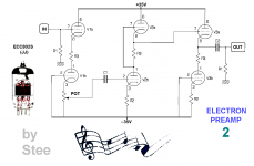
can you edit the drawing to be more clean?🙂
the reason why there is a stage before and after SRPP
it's because the load change the condition of source: i call that susceptibility🙄
that don't happens in Gomes configuration and also in current volume control
reversal SRPP is borne just to have a compensation of TTM - Triode Tone Mark
in current gain stages - Buffers
but is not a scientific thesis😎
Attachments
Last edited:
Nonsense
Broskie has a whole series on the SRPP, and he disagrees. Between Broskie and you, I choose Broskie.
What are you on about, have you actually read his articles? Broskie says exactly the same as I do! SRPP with no load is no longer an SRPP, and a real SRPP does not involve a cathode follower, and is really intended to drive a fixed load!Broskie has a whole series on the SRPP, and he disagrees. Between Broskie and you, I choose Broskie.
It's pretty easy to prove: imagine that in STee's circuit you moved the output from the upper cathode to the lower anode, how would operation differ?
Answer, almost not at all. Both gain and output impedance would be fractionally higher, but that's about it. That would never happen with an SRPP.
Even a quick search through one tubecad article:
No cathode follower in the SRPP:
http://www.tubecad.com/articles_2002/SRPP_Deconstructed/page3.html
http://www.tubecad.com/articles_2002/SRPP_Deconstructed/page6.html
Infinite load negates push-pull operation = not SRPP:
http://www.tubecad.com/articles_2002/SRPP_Deconstructed/page4.html
Last edited:
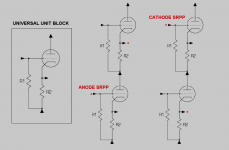
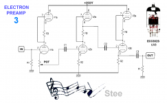
so to have this triode tone mark compensation
need two traditional SRPP with cathode output😛
need two traditional SRPP with cathode output😛
Attachments
Last edited:
- Status
- Not open for further replies.
- Home
- Amplifiers
- Tubes / Valves
- the Reversal SRPP