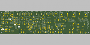
I am designing a good DIY preamplifier project to go with the class AB amplifier I made ( GitHub - profdc9/PowerAmpAudio: Power Amplifier based on Michael Chua's C300 amplifier ). It is at
GitHub - profdc9/PrettyGoodPreamplifier: A Pretty Good Preamplifier for Stereo and Subwoofer Use
I would like it to be constructed with relatively simple tools and readily available parts, with substitutes available. My github has many educational projects on it and I am working on audio projects that I hope will be both educational, simple to build, and useful as real equipment.
It is a stereo preamp with a subwoofer output. It has four unbalanced inputs selected by relays. It supports being remotely triggered to be turned on and remotely triggering other devices (the amplifier for example).
It has volume and a simple Baxandall tone control (treble/bass) and a relay to bypass the tone control. It has an adjustable low pass filter and gain for a subwoofer output. It also has balance control.
There are both unbalanced and balanced outputs for the stereo and subwoofer channels.
I was debating whether to use the THAT1646, but since there is a similar chip the DRV134, I think it is safe to include. Otherwise I might use a op-amp based balanced driver since substitution is easier for op-amps than balanced driver ICs.
If there's any interest or comments for such a project, let me know. The current PCB design and schematics are below.
Attachments
Last edited:
1. too low input impedance 5k (should be 10k to 100k)
2. not enough gain 12.8dB max (input can be 100mV to 2Vrms)
3. offset (switching noise, output >10mV)
4. why 2 faders in series? you rather need a level fader in each input to accommodate the wide input level range.
5. why no XLR input?
6. no need for a subwoofer output (most users will have an electronic xover. Many prefer driving the subs in stereo.)
7. inverted in/out
Last edited:
1. too low input impedance 5k (should be 10k to 100k)
I can add some series resistance to the input, but I think if the input impedance is too high, then the voltage noise at the op-amp begins to dominate. The output impedance of most sources shouldn't be much above 600 ohms right?
2. not enough gain 12.8dB max (input can be 100mV to 2Vrms)
I am not sure why this much gain is needed. Wouldn't a lot of gain could be dangerous for speakers because the amplifier would clip? Line level is usually 0.4 to 2.0 V or so, and so generally one wouldn't want to amplify it more than 4 times or so? But I could change the input gain if needed I suppose, for example R8/R9 from 22k to 47k.
3. offset (switching noise, output >10mV)
I am not sure what you are suggesting, perhaps an input AC coupling capacitor?
4. why 2 faders in series? you rather need a level fader in each input to accommodate the wide input level range.
Does this mean a different volume control for each audio source? Or does this mean both stereo inputs changing the volume of each separately with a different knob? I thought it was more convenient to change both stereo channels with single volume control and then fade between them.
5. why no XLR input?
For driving an amplifier, a small ground loop can cause significant hum because of the high gain (20-30 dB). I didn't think preamplifiers were supposed to have a high gain since they were going from line-level (with the exception of a phono preamp) to amplifier input level, actually usually attenuating the signal level for most common listening volumes. Therefore any hum introduced through the input tends to be attenuated as well, whereas if the same level of hum is introduced between preamp and amplifier, it will be more noticeable.
Also, it would make the board bigger. I would probably have to change one of the inputs rather than add one. I suppose one XLR input is better than none.
6. no need for a subwoofer output (most users will have an electronic xover. Many prefer driving the subs in stereo.)
I have a friend that wants one. But he may use a separate output anyways. It can't hurt to try it.
1. use the non-inverting input
3. your opamps can make around 1mV offset , with the baxandall on bass gain this will be in the 10mV range, so a click will be audible switching the tone control in.
Also the inputs might see some DC from phantom power. Yes a coupling cap. With the higher input impedance they can be relatively small.
4. RV1 and RV4 have the same effect, would be better to have a balance pot instead.
I talk about stereo pots.
5. see attachment

single pot balanced input control (Doug Self)

3. your opamps can make around 1mV offset , with the baxandall on bass gain this will be in the 10mV range, so a click will be audible switching the tone control in.
Also the inputs might see some DC from phantom power. Yes a coupling cap. With the higher input impedance they can be relatively small.
4. RV1 and RV4 have the same effect, would be better to have a balance pot instead.
I talk about stereo pots.
5. see attachment
single pot balanced input control (Doug Self)
Last edited:
I managed to squeeze in an XLR input for one of the channels using two THAT1206.
Could you explain further why RV1 and RV4 have the same effect? RV1 is an audio taper dual gang pot that attenuates both channels the same way. RV4 is a linear taper dual gang pot where the voltage divider of both channels is opposite, that is, the grounded side of the pot is opposite for both channels.
I see VOUT on the diagram you sent. Where is VIN?
Attachments
If RV1 is meant to be the balance pot, then the normal position is the 50% and will attenuate -14.8dB
in !00% it will still attenuate -9.54dB
in !00% it will still attenuate -9.54dB
Actually, the reason I would need a "preamp" is to boost 50 mv Moving magnet phono cartridges, with a RIAA curve. Or even MC. Line level inputs can be sent to the power amp with a "mixer" with all inputs on at the same time. Which input is powered up determines the signal out, not some redundant time wasting selector switch. BTW opposite phase outputs of "mixers" can be sent to power amps 100' away over twisted pair without noise buildup.
You could sell it at Bertha's Kitty Boutique. If Bertha's doesn't have it, then you probably don't need it.
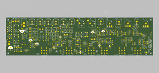
Pretty Good Preamplifier V2
Hello,
I have completed the Pretty Good Preamplifier V2. The main difference is that it completely eliminates a click when turning the amplifier on and off by grounding all of the outputs when the difference between +VCC and -VEE falls below 20 volts.
It has numerous features:
- Four inputs, one of which is a balanced input (THAT1206/INA137).
- Left and right channel outputs, both balanced and unbalanced (THAT1646/DRV134).
- A subwoofer output with an adjustable gain and cutoff frequency, also balanced and unbalanced outputs.
- Bass/treble Baxandall tone adjustment with tone adjust bypass
- Volume, balance control
- Can remotely switch relays with 12 volts, for remotely turning on and off an amplifier
- Can be turned on and off remotely.
- The opamps can be LM4562 or NE5532, there are 22 pF compensation capacitors to ensure stability with higher bandwidth opamps.
- All audio paths pass through relays rather than external switches so that noise pickup can not happen on the cables to the switches. It also tends to be more reliable (relays have sealed contacts). It uses the common G5V-2 telecom DPDT relays (HK19F can be used as well as an inexpensive alternative).
- Uses a 12 V center tapped toroidal transformer for good isolation.
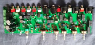
It's all through hole and can be assembled without exotic tools. A picture of the finished board is below.
Hello,
I have completed the Pretty Good Preamplifier V2. The main difference is that it completely eliminates a click when turning the amplifier on and off by grounding all of the outputs when the difference between +VCC and -VEE falls below 20 volts.
It has numerous features:
- Four inputs, one of which is a balanced input (THAT1206/INA137).
- Left and right channel outputs, both balanced and unbalanced (THAT1646/DRV134).
- A subwoofer output with an adjustable gain and cutoff frequency, also balanced and unbalanced outputs.
- Bass/treble Baxandall tone adjustment with tone adjust bypass
- Volume, balance control
- Can remotely switch relays with 12 volts, for remotely turning on and off an amplifier
- Can be turned on and off remotely.
- The opamps can be LM4562 or NE5532, there are 22 pF compensation capacitors to ensure stability with higher bandwidth opamps.
- All audio paths pass through relays rather than external switches so that noise pickup can not happen on the cables to the switches. It also tends to be more reliable (relays have sealed contacts). It uses the common G5V-2 telecom DPDT relays (HK19F can be used as well as an inexpensive alternative).
- Uses a 12 V center tapped toroidal transformer for good isolation.
It's all through hole and can be assembled without exotic tools. A picture of the finished board is below.
Attachments


- Home
- Source & Line
- Analog Line Level
- The Pretty Good Preamplifier