😀C26 and C9 cause cross-conduction
It's not like that.The opposite is true. Everything can be checked.
With and without C26 /C9 capacitors.class AB+С . Is there a difference ? The AB+C mode is specially taken for the purity of the experiment, when the output transistors are closed.
In the composite, the level of distortion is minimal,I specifically took a simplified basic version for better visibility.
In the composite, the level of distortion is minimal,I specifically took a simplified basic version for better visibility.
Attachments

Last edited:
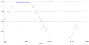
1kHz 36Vpp 8R
Attachments
Last edited:
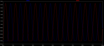
This dimension is known to me.Here it is. Convergence with and without capacitors1kHz 36Vpp 8R
Attachments

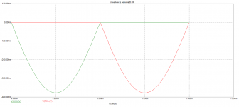
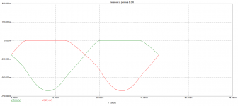
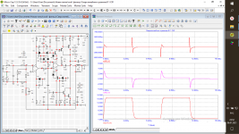
>at 100Hz 36Vpp 8R 0.8A cross-conduction. Who thinks it's okay ?
What is max cross-conduction that would be acceptable/good?
What is max cross-conduction that would be acceptable/good?
IMHO, for true Class-B, almost zero, 0-100kHz at least
for Class-AB, the idle bias current, 0-100kHz at least
for Class-AB, the idle bias current, 0-100kHz at least
Last edited:
Everything determines the spectrum of distortion and the rate of voltage rise . Communication distortion is very good at suppressing oos .The rest is from the evil oneIMHO, for true Class-B, almost zero, 0-100kHz at least
for Class-AB, the idle bias current, 0-100kHz at least
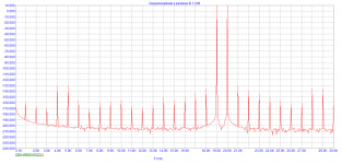
10hertz C9-100mk/100u. 1500mV input. Rated power mode
By the way, these capacitors С9/С26 eliminate the possibility of a through current VC .
Attachments
Last edited:
1kHz 36Vpp 8R
C5 in your drawing is reduced by 3 times ,post 24 . Why?
in general, the circuit is not very stable;
when C5 is > 330p and C10 is removed oscillation occurs on square waves
when C5 is > 330p and C10 is removed oscillation occurs on square waves
And why delete C10 from your drawing ?in general, the circuit is not very stable;
when C5 is > 330p and C10 is removed oscillation occurs on square waves
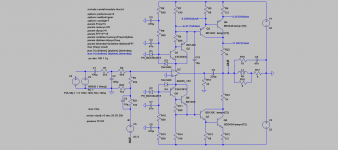
Let me clarify. In the power supply of opamp pairs A1016/C3502 and C1815/A1380
Last edited:
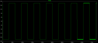

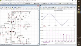
Let's move on to the composite version.Also, the operating mode of the amplifier is pure class B . R2 simulation of the DC voltage adjustment circuit at the output of the amplifier. The clip at 1kHz and 20khz is clean, good limitation .
Attachments


Last edited:
- Home
- Amplifiers
- Solid State
- The power amplifier in the mode B.