I think most people are probably aware of these, but I would like just to inject a bit of physics into the "why".
If you have two inductors, you probably want to place them such that there will be minimum coupling between them.
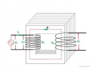
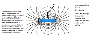
First of all, a transformer is a perfect exampling of intentional inductor coupling , that is you want as much coupling as possible. The flux of one inductor will couple almost all of it to the adjacent inductor. Not only that, but there is usually an iron core inside each transformer as to maximize coupling. See pic.
If you have two inductors, you probably want to place them such that there will be minimum coupling between them.
First of all, a transformer is a perfect exampling of intentional inductor coupling , that is you want as much coupling as possible. The flux of one inductor will couple almost all of it to the adjacent inductor. Not only that, but there is usually an iron core inside each transformer as to maximize coupling. See pic.
Attachments
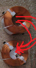
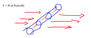
But if you have two inductors on a xover board, placement like the above is probably very bad. On an xover board, you want the complete opposite – that is you want as little coupling as possible. The first attachment shows a non-ideal placement. You can see that the flux of one inductor gets coupled almost all of it two the adjacent inductor (see the flux line drawn).
The next two attachments show a more ideal example that is most recommended as most people here would usually do. But what is the physics behind it?
The next two attachments show a more ideal example that is most recommended as most people here would usually do. But what is the physics behind it?
Attachments
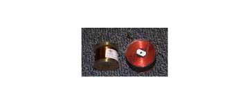
It has to do with Lenz's law. If you have a wire and a changing flux perpendicular to the wire, an current will be induced like these along the length of the wire – see attachment. But a wire is a 3 dimensional thing so you have current not just along the line, but all over the wire. In this case, since the flux is perfectly perpendicular to the wire, the current is along the wire length, BUT that is not always the case, and it certainly depends on the direction of the flux. In general, the induced current is always perpendicular to the flux.
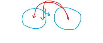
This is the case when you place two inductors side by side. That is the flux line is 90 degree (perpendicular) from each other. I tried to draw them on the second attachment, but you probably have to visualize 🙂
This is the case when you place two inductors side by side. That is the flux line is 90 degree (perpendicular) from each other. I tried to draw them on the second attachment, but you probably have to visualize 🙂
Attachments
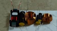
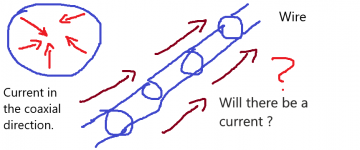
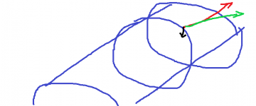
But what if you have the flux that moves along the length-wise of the wire, will there be a current? The answer is “YES”, but since the wire is a 3 dimensional thing, you will have a current coaxialy inward (and outward of course), but not in the direction of the wire. See attachment. This is the case when you place two inductors perpendicular like these. And this is what usually recommended.
Attachments
How much affect will these inductors coupling, even if you place them as recommended, to each other because we saw that there is still a current induced albeit coaxially?
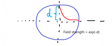
Luckily, Gauss law will come to the rescue. Gauss law says that there is very little field inside an inductor, and most of the current is on the surface. So when you (unintentionally) tries to induce a current coaxially on a wire, you probably won't get very far because it will take a lot of flux to generate a coaxial current. See the attachement.
As you can see, Gauss law says that the field strength drops off significantly inside the inductor. Exp(-ad), d is the depth of the inductor, will approach zero very quickly. a is some constant dependent of the type of inductor. The larger the "ad" term, the faster the field will drop off.
Attachments
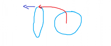
In the end, you probably have something like these. The current component on the surface will be much larger compared to the coaxial direction, so the cross-coupling will be very minimal. The "green" line is the overall current direction and should be much stronger vs. the "black" coaxial component.
Attachments
andy2. Very interesting.
The reason we all keep inductors apart, and align them perpendicular, is so their values don't change. We believe an exact value will give us a 'better' crossover.
For woofers, Tony G of humblehomemadehifi.com recommends cored inductors. I use cored inductors in all my 4-ways (woofers only).
Let's look at your drawings;
1) if I put two cored inductors side be side, are you saying they will be 'stronger'?
2) do I try to align the currents? or do I turn one 'backwards' so the currents are in opposite directions?
3) if music is an alternating current, and the rising part of the sinusoidal waveform is in the opposite direction of the falling portion of the waveform, will the two aligned inductors work better when aligned identically, or should they be opposite.
Looks like a great experiment for my next build.
Physics, start googling electromagnetism. When electric charge starts moving there will be a magnetic field. So, audio in your inductor, being changin ac voltage, will introduce changing magneticfield around the inductor. Note, this is not specific to inductors but all conductors like wires, chassis etc that can carry electric current. Now, the thing works backwards as well, changing magnetic field will induce current to a conductor (loop). Check out lenz law, faradays law etc. One evening browsing youtube will get you started.
Basically, your inductor is a giant loop, and there is magneticfield like a donut around it. If you put another inductor next to it, some of the magnetic field lines will pass through the other inductor and induce current to it. Put the another inductor another way around, so that magnetic field flow lines don't through the other inductor and no current is induced. Have fun learning!🙂
Basically, your inductor is a giant loop, and there is magneticfield like a donut around it. If you put another inductor next to it, some of the magnetic field lines will pass through the other inductor and induce current to it. Put the another inductor another way around, so that magnetic field flow lines don't through the other inductor and no current is induced. Have fun learning!🙂
Your explanation sums it up well. All one needs to know is some basic high school physics. 🙂Have fun learning!🙂
OK, here is a bit of a fun thing while you're drinking your beers ...
At the back of my house, there are a bunch of power line cables running at 60 Hz from the electrical company to provide power to the neighborhood. Now if I were to build an giant inductor that captures the power from the electrical company (like an transformer), will it be legal? I mean I am not touching the cable lines physically?
YES or NO?
Troels tests are interesting, but it seems he's only measuring the change in value, but others have measured actual signal coupling and distortion in some circumstances.
Keep signal conductors out from on top of and under coils. 🙂
Best,
E
Keep signal conductors out from on top of and under coils. 🙂
Best,
E
- Home
- Loudspeakers
- Multi-Way
- The physics behind inductor placement on xover board