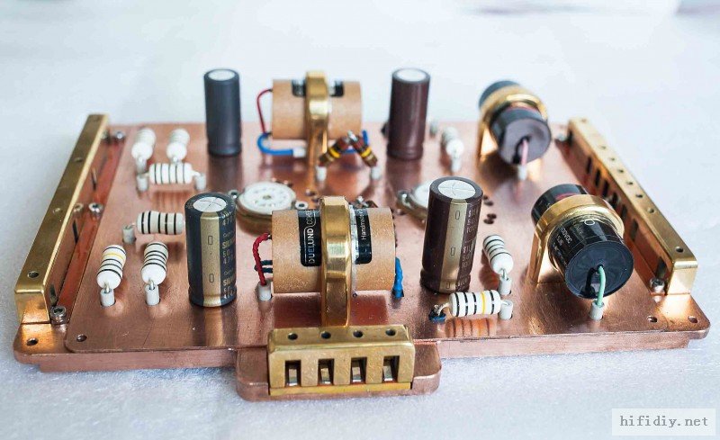
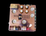
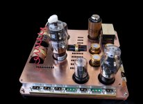
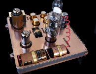
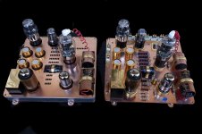
In my spare time for two years, I DIY the power module and amplifier module of the tube preamplifier
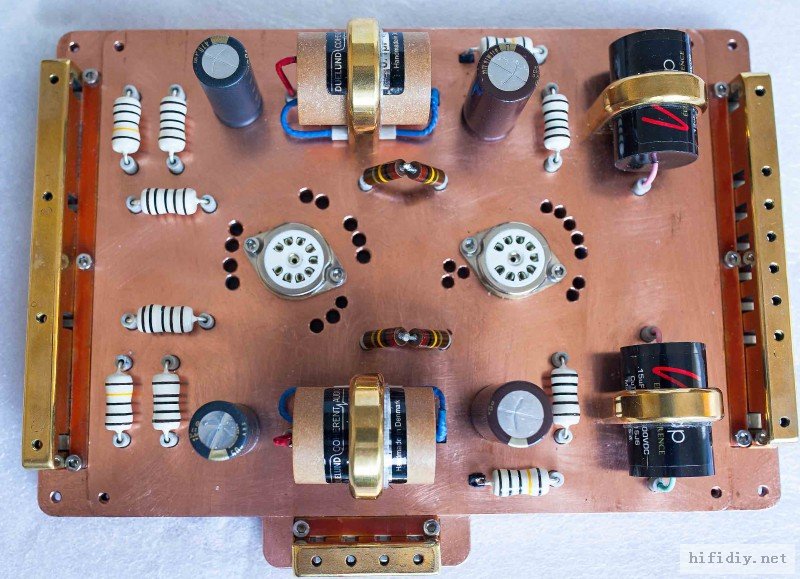
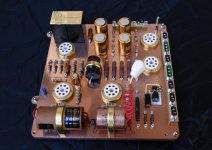
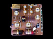
Amplification module

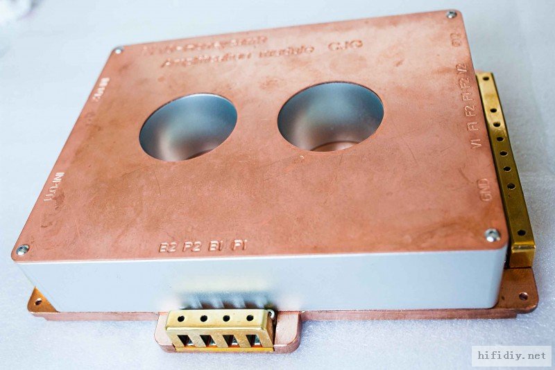
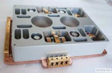
Power module
Amplification module
Power module
Attachments
-
 012445a9yzltb357dch7vc.jpg83.3 KB · Views: 1,397
 -
 012446k8jjx3x33zj47gmx.jpg120.2 KB · Views: 960
 -
 012835yvquyt3smcppquzu.jpg68.2 KB · Views: 978
 -
 013256v1q2j7q1d1ajfgjr.jpg70.2 KB · Views: 975
 -
 IMG_6902.jpg409.6 KB · Views: 217
 -
 IMG_6903.jpg244.7 KB · Views: 237
 -
 IMG_6905.jpg764.8 KB · Views: 300
 -
 IMG_6907.jpg575.7 KB · Views: 319
 -
 IMG_6911.jpg486 KB · Views: 265
 -
 IMG_6916.jpg476.2 KB · Views: 284
Last edited:
Attachments
Fantastically excellent and wonderful.
You can describe it to us in terms of design and the tubes ?🙂
You can describe it to us in terms of design and the tubes ?🙂
What is the frequency response of this amp as it has a lot of shielding adding capacitance to each connection?
It looks to me that this amp was not build to perform well only to look good.
It looks to me that this amp was not build to perform well only to look good.
Hello, Lampie519, this is the audio note m10 signature price, re-engraving the circuit DIYWhat is the frequency response of this amp as it has a lot of shielding adding capacitance to each connection?
It looks to me that this amp was not build to perform well only to look good.
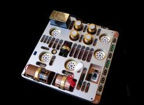
You won the bet. Many people think that this design will shield high frequencies and various problems. When I tested it, I was shocked by its sound. The background is very quiet, the treble is floating, the sound field is open, and the sense of space is strongWell it looks good, I’ll bet it performs well too. Nice build
In the past, my DIY circuit boards were made of insulating boards. Compared with it, the sound has been greatly improved, the sound is clear, and there is no sound of electric current.
and there is no sound of electric current.
How does electric current sound?
Btw, I think this showcase should be in the Sticky Photo Gallery thread 🙂
It's mostly true with semiconductor circuits as they have huge open loop gain and tons of feedback.With tubes even if it has feedback , the open loop/closed loop ratio is very small and bigger capacitances are allowed...tubes internal capacitances are also very small compared to most audio range silicon components...You can OVERDO circuts with lesser drwbacks when working with tubes.If no global feedback than the more shielding the better as bandwidth won't suffer too much anyway...What is the frequency response of this amp as it has a lot of shielding adding capacitance to each connection?
It looks to me that this amp was not build to perform well only to look good.
Last edited:
We do make these DIY creations to listen to art as well. Distortion overly stylised for no reason other than for the art of it. Music has no engineering purpose.
And this thread is not about product for sale but one persons individual creation made for him. I thank him for sharing.
And this thread is not about product for sale but one persons individual creation made for him. I thank him for sharing.
As far as Im concern Oufeng's build is very impressive considering that it's a diy effort.
I imagine if this was a commercial product made in the West it'll probably will garner lot's of rave in the audio press be it hype or not.
I imagine if this was a commercial product made in the West it'll probably will garner lot's of rave in the audio press be it hype or not.
it seems care has been taken to insulate wires and joints with spacers etc. But Isn't it risky having high voltages solder joints in carved out slots of copper sheet ?
As far as Im concern Oufeng's build is very impressive considering that it's a diy effort.
I imagine if this was a commercial product made in the West it'll probably will garner lot's of rave in the audio press be it hype or not.
Agree on all counts.
My personal preference based on sound is towards lighter and less metallic constructions, but this effort is still amazing. Hats off.


I think it's is beautiful. Having just re read the description, as a preamp and power supply the construction does not seem inappropriate. If it was me I would be a little more generous with the creepage and clearance but whatever. I don't know if you were aiming for a steampunk type of look??
Woof tough crowd around here.
Oufeng - thank you for sharing your efforts, the machine work is impressive. I go to great lengths to make my personal designs visually appealing, there is nothing wrong with that. At the end of the day, this hobby is about enjoyment of music and pride in the things you create, so if that is accomplished then the work is a success 🙂
Oufeng - thank you for sharing your efforts, the machine work is impressive. I go to great lengths to make my personal designs visually appealing, there is nothing wrong with that. At the end of the day, this hobby is about enjoyment of music and pride in the things you create, so if that is accomplished then the work is a success 🙂
Big bow to Oufeng for a marvellous looking piece of diy.
It´s really boring to always see some members here with nothing better to do
than trashing someone else´s diy effords instead of producing something themselves.
Y´all seem to forget the "Joy of Ownership".
If having to chose between a product that sounds and looks awesome or a product that sounds awesome and looks like crap...... I know what I´d prefer in my living room, having to look at it every time I play music.
Concrete slabs inside a boom box has no relevance in a thread like this. Shame on the members with negative attitudes.
Luckily, some have constructive criticism regarding space between shielding and powerlines.
A bit bonkers design wise but it does look nice, not really my bag with all the fancy caps showing their knickers but fair play to you for effort and thinking out of the box. Must have taken ages to fabricate, could we see the schematic?
In one of your pics of the bottom with all the routing/tunneling going through the copper it looks like there's quite a few spots where arching has occurred, a possible problem stressing the PSU? Can't see any mains earth, the lads at Elf & Safety or the Spanish equivalent might be having caniptions if they got their hands on it. Not having a go, am attempting constructive criticism.
Lastly any chance of a few pics of the power supply?
Andy.
Last edited:
Just look at the components used, better we not ask Oufeng how much it cost for the copper plates machining work & cnc alum block. Lol. Thinking about it the weight + the sandwich design may actually contribute lots to good sound. I once help a friend build 2 6sn7 preamp p to p but one was on fiberglass the other on phenolic board, everything else was the same & strangely the phenolic version sound smoother overall, till today still thinking if it was due to different damping between the boards that made the difference.
- Status
- Not open for further replies.
- Home
- Amplifiers
- Tubes / Valves
- The perfect combination of sound and craftsmanship