Any 220k will do fine.
Panasonics are good metal film resistors. The Vishay Dale resistors are good to. The ones you found are fine.
Uriah
Panasonics are good metal film resistors. The Vishay Dale resistors are good to. The ones you found are fine.
Uriah
After reflowing every solder joints and not seeing any improvement, I'll swap the IC's starting by socketing the LM318 and if nothing happens, I'll buy a new LM3886.
This board may have seen 50 VAC during my first testing because my PGnd connection was faulty. Everything might come from there...
One more symptom though... Only when my Audio In is grounded, the heatsink,wich tested to be perfectly insulated, makes the channel Hum when touched by hand. The other board is not sensitive to this issue.
I just finished soldering all components. I picked up a pair of 220K .25W resistors at Radio Shack just after noon. My hook-up wire arrives tomorrow. I built a dim bulb tester this weekend. Can't wait to fire these babies up.
Here are pictures of the boards.
Martin
Here are pictures of the boards.
An externally hosted image should be here but it was not working when we last tested it.
An externally hosted image should be here but it was not working when we last tested it.
Martin
jERiCOh-
Sorry I try to stay away from the pC on the weekends.. I will look at your photos and comments tomorrow.
Martin-
It is my "suggestion" that you trim your leads closer. Long leads touch each other or the enclosure when mounting.
Sorry I try to stay away from the pC on the weekends.. I will look at your photos and comments tomorrow.
Martin-
It is my "suggestion" that you trim your leads closer. Long leads touch each other or the enclosure when mounting.
troystg said:It is my "suggestion" that you trim your leads closer. Long leads touch each other or the enclosure when mounting.
I am open to any and all "suggestions." 😉 I may have just turned 50 but I am just a beginner. I wish I had started sooner cause my eyesight is nowhere near what it used to be.
 I have a 10x loop I used to check my solder joints. None of the leads are touching but some are rather long. I may carefully do a little bit of trimming. I have 1/2" stand-offs and will be mounting these in a wood case with aluminum front, dividing and rear panel and a perforated aluminum top.
I relied heavily upon documentation and other's pictures when assembling the boards. I had never soldered anything except copper pipe before. Total time spent to solder all components was about 3 hours.
Martin
Nice work Martin! 😎
I second Troy. Some flush side-cut trimmers are perfect for this job. I trim my leads down to the top of the solder joint, FWIW.
My boards are at the same stage as Yours. Trafos arriving in the post very soon, and then...... Ignition (or hopefully NOT! )
)
Cheers
Jon
I second Troy. Some flush side-cut trimmers are perfect for this job. I trim my leads down to the top of the solder joint, FWIW.
My boards are at the same stage as Yours. Trafos arriving in the post very soon, and then...... Ignition (or hopefully NOT!
)Cheers
Jon
Things are looking good you guys. Nothing beats the thrill of firing them up, hearing the relays click and ....music! Sweet! Mine are still on the board while I dream of a case for them.
They are playing now and sounding great, they have been playing music at a moderate volume for 7 days, they should be burnt in. I notice on my live stuff that the sound stage is nice, accurate, the highs have a crisp quality but not harsh, mids are smooth and I like the vocal timbre. All around nice upgrade from my Musical Concepts modded Hafler DH-200 and the Parasound MCA-500 too. I like the sound it makes!
Now on to my Pre Amp, well buffer / attenuator / switcher.
Martin, your local RatShack should have a nice pair of nippers for a good price, then you can nip those leads down with ease.
jonclancy said:Trafos arriving in the post very soon
And they're here - special dispensation for expenditure from The Boss!! Normally, I'd just sling 'em on and fire it up. 😀 But this time, I'm going to make my dim-bulb tester first!!

Can't wait to hear these amps!!
Cheers
Jon
jERiCOh said:My readings just in case:
Pink noise board:
-2.60mVDC, 3.30mVAC
Dead silent board:
+0.31mVDC, 0.75mVAC
0.75mVac is not dead silent.jERiCOh said:
My retake with jumpered inputs:
-2.50 mVDC, 9.62 mVAC (Noisy board)
+0.40 mVDC, 0.07 mVAC
Your second set of figures showing <0.1mVac qualifies as silent for a power amplifier.
jERiCOh said:After reflowing every solder joints and not seeing any improvement, I'll swap the IC's starting by socketing the LM318 and if nothing happens, I'll buy a new LM3886.
This board may have seen 50 VAC during my first testing because my PGnd connection was faulty. Everything might come from there...
One more symptom though... Only when my Audio In is grounded, the heatsink,wich tested to be perfectly insulated, makes the channel Hum when touched by hand. The other board is not sensitive to this issue.
Touching the HS should NOT have an affect on the sound.. I am still inclined to think bad connection or silicon.
Possibly ground loop, but that is usually band limited and not "pink / white noise"
I think what he thinks. I think try the dmm and check resistance from sink to tab of LM3886 and from sink to ground and from tab to ground. Do this with no power to the amp. Check sink and tab to signal ground as well. Its in there somewhere.
Ri
Ri
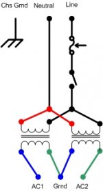
I have a question about wiring an AnTek AN-2225 toroidal transformer to the Rev C board. (toroid wiring attached)
I am using a filtered IEC C14 connector. I have the two red input wires from each toroid (4 wires total) attached to the 125V hot and the two black input wires from each (4 total) attached to the 125V negative. I have a separate green wire to the power ground.
I measured continuity on the secondaries on each transformer and combined a non-connected green and blue pair to PGND. I then have the other green attached to AC1 and the other blue attached to AC2. AC1 and AC2 now measure as continuous through the combined PGND.
Is this the correct wiring? I plugged my input, switch and toroids into my dim bulb tester sans boads and the 15 watt bulb glowed dimly. I measure 22V on each toroid between what I have labeled AC1 & PGND and AC2 & PGND.
Thanks,
Martin
Attachments

After testing everything up there, I finally found something. Tab of the LM3886 is seeing the Input ground, 457ohm to be precise. There is no other short.udailey said:I think what he thinks. I think try the dmm and check resistance from sink to tab of LM3886 and from sink to ground and from tab to ground. Do this with no power to the amp. Check sink and tab to signal ground as well. Its in there somewhere.
Ri
mhconley said:I have a question about wiring an AnTek AN-2225 toroidal transformer to the Rev C board. (toroid wiring attached)
I am using a filtered IEC C14 connector. I have the two red input wires from each toroid (4 wires total) attached to the 125V hot and the two black input wires from each (4 total) attached to the 125V negative. I have a separate green wire to the power ground.
I measured continuity on the secondaries on each transformer and combined a non-connected green and blue pair to PGND. I then have the other green attached to AC1 and the other blue attached to AC2. AC1 and AC2 now measure as continuous through the combined PGND.
Is this the correct wiring? I plugged my input, switch and toroids into my dim bulb tester sans boads and the 15 watt bulb glowed dimly. I measure 22V on each toroid between what I have labeled AC1 & PGND and AC2 & PGND.
Thanks,
Martin
Red+Red------0000------Green
.................. 00000-----Blue+Green
Black+Black---0000------Blue
So, your signal ground comes into the board right there near the sink. If it is touching the sink somehow then thats bad plus that means that your LM3886 is not insulated from the sink. The problem that will develope rather quickly when you put it in a chassis will be that the LM3886 will see ground through the sink and it will fry on the spot. If your chassis is grounded which wont get by our AndrewT, I guarantee it 🙂
Uriah
Uriah
Well actually what is amazing about that is that the LM3886 is perfectly insulated from the sink and the DMM is proving it. I unscrewed the sink just to make sure. The problem might come directly from a faulty chip or a short.
If you have to replace the chip you can get them from Digikey and make sure to get the TF package. I think thats all I will buy from now on. Fully insulated package. I have burnt to many of the chip amps from letting a sink touch something grounded.
Well, I am off to bed.
Uriah
Well, I am off to bed.
Uriah
mhconley said:........................
Thanks,
Martin.................
Attachments
OK - I have it wired correctly. Thanks Jericoh & Troy.
Should the 15 watt bulb in my dim bulb tester be glowing when only the transformers are hooked up? (Power leads are not plugged into the boards.) It is lit very dimly.
Martin
Should the 15 watt bulb in my dim bulb tester be glowing when only the transformers are hooked up? (Power leads are not plugged into the boards.) It is lit very dimly.
Martin
- Home
- Amplifiers
- Chip Amps
- The new "My Ref" Rev C thread