This is a mosfet construction I did about two years ago. I actually presented it on the "Post your solid state pics here" together with another amp, but I think I must talk a bit why I think it's anything to build for DIY-ers.

It's a robust and simple construction, but it's not made simple for it's own sake.
This forum is very diverse. We have one group of guy's, the rationalists. They are usually very skilled in analysing every aspect of amplifier design, and their goal normally is to reduce the THD to the very possible minimum: An example of that is the "Honey Badger" DIY amp. It maximises the concept that Douglas Self described as a "blameless amplifier". I haven't seen any specs on it, but it has without any doubt very low THD.
On the other hand we have the subjectivists. They usually build amps that are designed with the most common hobby-horses that are circulating in the audiophile universe. Such as simplicity, class A, single ended designs and low or no negative feedback( NFB). Usually rationalists looks at these things with some scepticism. These kind of projects are often based on some design of Mr Nelson Pass, since he seems to encourage people to build clones of his amps, such as Aleph, Zen, First Watt and so forth.
If a skilled designer looks at the diagram, he will probably wonder what R1 is doing. Normally there is just a capacitor on the VAS that limits the bandwidth. And why this massively biased differential stage? It draws about 25mA on each half.
OK, now I must declare that I belong to the subjectivist school, at least I have one leg there. I used to be inspired by Nelson and his minimalistic amps. He tends to use amps with drain output, such as Aleph, First Watt F5, but I decided to build a source follower, since that type of amp usually has higher damping factor, without using a lot of global NFB. This amp is designed to be as simple as possible without compromising any parameters. I mean, you could build even a simpler one but then it wont measure so well.
Here comes the explanations.
The point with using a resistor in the VAS is that the amp should have the same amount of NFB over the entire audio range.
Because of this, the differential stage has to be very high biased, so that it doesn't distort too much. The resistor will namely load the diff stage quite heavily.
As a good side effect of this, the VAS ( voltage amplification stage)will have an unusual low output impedance - around 300 ohm. So there won't be any need for a buffer stage. Well many mosfet amps usually don't have buffer transistors between the VAS and output mosfet's. The global NFB will take care of any hf drops due to high capacitances in the output devices.
Why a constant amount of NFB over the entire audio range? I among others believe that this is crucial for obtaining the right "body" to instruments, and so that the amps doesn't sound overly bright. When the NFB is frequency dependent, the distortion rises linear with frequency. Our ears - or perhaps more accurate - our brain perceives this as a kind of brightness. An instrument produces a base tone and a lot of overtones, and if the dist rises with frequency, the "tonal bodies" tilts towards brightness.
But if we could make an amplifier that had so much feedback that it virtually obliterated any THD? There are such amps. There is a German brand named S.A.C. They have made an amp that has a mind blowing 80dB of feedback over the entire audio range. That's a real feat, I have no idea how they managed, from a engineers point of view. The site “6moons” reviewed it and they described the sound as “utterly dry” with a slamming bass.
Back to the amplifier. Normally the global feedback is supposed to correct very many things, such as hf drops in the output mosfet's. But the low impedance of the VAS, sees to that the global NFB isn't so much involved in correcting these things. We have a robust differential stage and a VAS that has a very short local feedback loop that reduces distortion. This stage drives the source follower output mosfet's. A source follower can actually be considered as an amplifier that has an extremely short feedback loop from the source to the gate.
The open loop gain is around 250 in absolute terms, so the amount of NFB is a moderate 10 times, or 20dB. The device is intended to work in partial class A - around 0.5A to 1A is sufficient.
Measurements. I haven't done any on the real thing, but I have simulated it. The bandwidth is about 500khz. At 10V Rms with 8 ohms load, the THD is around 0.03%.
But observe! The THD is exactly the same, regardless of frequency. A 20khz signal still gives 0.03% with approximately the same type of harmonics as when measured with a 1khz source.
To sum things up. When I constructed this amp I used two hobby-horses, that may be considered unproven.
Firstly that low NFB is a good thing.
Secondly that few active components usually sounds better than many of them, even if the THD is higher in absolute terms.
Many would agree that a single ended triode sounds good, even if it has 5% of 2:nd order harmonics. Rationalist usually says that this and that is impossible to hear. 0.0001 % of THD may sound impressive, but who knows how sensitive our ear/brain is to find out subtle patterns?
I will give an example. In a DAC re-clocker I made, I had to deal with the fact that the source becomes out of sync with the master clock after a while. I solved this( at 96khz rate) with inserting duplicate samples or removing samples in order to adjust the buffer size. Usually such one-sample adjustments took place about once a second. This was actually heard on soft music as small subtle ticks once and a while. So I made a linear interpolation, and furthermore, I made these interpolations at samples with low amplitude.
The anomalies still could be heard. After some while, I found out that it was the insertion itself that caused a time related distortion. It, so to speak, fast forwarded the data stream by one sample, and that was heard.
So I decided to bring forth the heavy artillery. I designed an oversampling algorithm that gradually interpolated the injected sample into the stream over 32 consecutive samples, and now the artefacts were gone.
One more thing about THD. Many op amps has THD figures down to 0.001 %. But I have never really managed to do something good out of opamps. Despite their low distortion, they still degrades the perceived sound in some way. I used a buffer with the OPA628 (~$35). It did sound impressive, but after a while a feeling of hollowness grew stronger. So I replaced it with a mosfet source follower, class A biased, and now the sound became more digestible - the "hifi" touch was gone, even though the circuit now distorted more. But this may of course be a placebo thing. Everything I have written may be a placebo hallucination. Yes, even the "blameless amplifier" may be an illusion.
This blameless amplifier thing. Isn't that a bit like marrying a girl so that she will become a good and "blameless" wife?
Finally, I think my construction sounds really good.
If you want to build it, I have documents on google drive:
https://drive.google.com/folderview...hhNWNsQ0xuelFDeWZMZTFONmg0bUJzMGc&usp=sharing
An externally hosted image should be here but it was not working when we last tested it.
Last edited:
Very nice Henrick and for you to write this up and document. Some simple objective test (square wave, sound card based thd etc) when you have time would be nice.
I agree with much of what you say - just one thing worth mentioning is that amp with fet input diff stage is ime very sensitive to preamp. Hi-z preamp like some tube amps sound ..heavy and sometimes a bit muddled soundstaging wise. But with another preamp - this "veil" just disappears 😉)
Thanks for sharing your work 😉
Last edited:
It's a nice piece.
Two items:
1) Some of my designs are Common-Source outputs, but note that I make
the bulk of my income on Common-Drain mode.
2) Investigate a better P channel part than the IRF, noted for some
transconductance shelving vs frequency that particularly shows up in the Vas
(in reality, not simulation). Same part from other mfrs usually does not have
that.
😎
Hi, Nelson - I'm honoured.
Interesting to hear about that p-channel issue you mention. Are the IRF9540 also suffering from these phenomena or is it only the IRF9610 that has these anomalies? Didn't you have those types on the diff stage on Aleph? But on the other hand, they didn't have full voltage swing on their drain.
You're mentioning other manufacturers. I thought the IRF devices were made by different mfrs. Perhaps you could suggest something? I can't really go to my local dealer and ask him to give me some p-channel mosfet that doesn't suffer from transconductance shelving. 🙂
This leads to another thing I have been wondering about over the years. Almost every DIY mosfet project uses the IRFP240/9240. Personally, I tend to build amps around the IRF540/9540 or perhaps 530/9530, and I think it sounds good.
The obvious advantages with these 240/9240 is that they dissipate more heat, and can withstand higher voltage. But this regarded, are there some other arguments that makes them "better". Do they empirically, "sound better" or anything like that. Perhaps the complementary pair is better matched. But on the other hand, on class A devices, isn't it a bit overkill to match the output pairs? Doesn't a mismatch just give some healthy 2:nd order dist?
I haven't that practical experience regarding various components, I look in the datasheets and choose from what I see there.
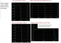
OK, kasey197, you wanted to see some figures, like square waves. In my opinion square waves doesn't say much about the actual amplifier's audio behaviour, since a square wave puts the amplification stages in a state they never operates in normally. The feedback path puts out of order in the transients. But it might be of some interest to watch how the amp recovers from those un-normal states. So I have attached some curves from a spice emulation.
They look quite fine, but when I run the square wave without input LP filter and with a 1uF capacitor on the output, in parallel with an 8 ohm load, one can observe a massive overshoot on the positive edge - it's the diff stage that gets saturated. But the good thing is that it recovers quickly into equilibrium, and without much ringing, and that suggests good stability. But remember, these overshoots never occurs in real life.
I have also attached some THD figures. The curves looks almost the same at both 1khz and 9khz. The latter shows an increase of the 3:rd harmonics from around 0.007% to 0.02%. But these figures are theoretical.
The measurements are made with a bias current of around 1A.
Interesting to hear about that p-channel issue you mention. Are the IRF9540 also suffering from these phenomena or is it only the IRF9610 that has these anomalies? Didn't you have those types on the diff stage on Aleph? But on the other hand, they didn't have full voltage swing on their drain.
You're mentioning other manufacturers. I thought the IRF devices were made by different mfrs. Perhaps you could suggest something? I can't really go to my local dealer and ask him to give me some p-channel mosfet that doesn't suffer from transconductance shelving. 🙂
This leads to another thing I have been wondering about over the years. Almost every DIY mosfet project uses the IRFP240/9240. Personally, I tend to build amps around the IRF540/9540 or perhaps 530/9530, and I think it sounds good.
The obvious advantages with these 240/9240 is that they dissipate more heat, and can withstand higher voltage. But this regarded, are there some other arguments that makes them "better". Do they empirically, "sound better" or anything like that. Perhaps the complementary pair is better matched. But on the other hand, on class A devices, isn't it a bit overkill to match the output pairs? Doesn't a mismatch just give some healthy 2:nd order dist?
I haven't that practical experience regarding various components, I look in the datasheets and choose from what I see there.
OK, kasey197, you wanted to see some figures, like square waves. In my opinion square waves doesn't say much about the actual amplifier's audio behaviour, since a square wave puts the amplification stages in a state they never operates in normally. The feedback path puts out of order in the transients. But it might be of some interest to watch how the amp recovers from those un-normal states. So I have attached some curves from a spice emulation.
They look quite fine, but when I run the square wave without input LP filter and with a 1uF capacitor on the output, in parallel with an 8 ohm load, one can observe a massive overshoot on the positive edge - it's the diff stage that gets saturated. But the good thing is that it recovers quickly into equilibrium, and without much ringing, and that suggests good stability. But remember, these overshoots never occurs in real life.
I have also attached some THD figures. The curves looks almost the same at both 1khz and 9khz. The latter shows an increase of the 3:rd harmonics from around 0.007% to 0.02%. But these figures are theoretical.
The measurements are made with a bias current of around 1A.
Attachments

Svitjod, as far as I know, the issue afflicts the 92xx, 95xx and 96xx series PMOSFETs made by IRF. Possibly other series are similarly affected.
"IRF" devices made by other companies don't show the kink.
hth, jonathan
"IRF" devices made by other companies don't show the kink.
hth, jonathan
OK, regarding that most IRF's sold today are made by Vishay, this shouldn't be a problem. Furthermore, in some document Nelson wrote about mosfet's, he toned down the problem. And in this particular circuit, that p-channel device will be linearised by the local feedback loop even before the global NFB takes care of it. But of course, the IR brand should be avoided in this case.
Perhaps someone has any comment about the usual choice of output devices among DIY-ers. Has the IRFP240/9240 some other advantages over the IRF540/530/9540/9530 devices more than larger casing and higher voltage rating? And of course the Crss, but this circuit is very insensitive to high miller capacitances due to the low output Z of the VAS.
I'm using alu-oxide insulators, normally. With those, each TO220 will dissipate at least 15W without any problem.
thanks for the writeup and sharing your thoughts.
fairchild also is a popular supplier of vertical mosfets, at least on this side of the pond.
mlloyd1
fairchild also is a popular supplier of vertical mosfets, at least on this side of the pond.
mlloyd1
Why a constant amount of NFB over the entire audio range? I among others believe that this is crucial for obtaining the right "body" to instruments, and so that the amps doesn't sound overly bright.
And why would there be any brightness added..?..
By the mechanism you point below ? :
When the NFB is frequency dependent, the distortion rises linear with frequency. Our ears - or perhaps more accurate - our brain perceives this as a kind of brightness. An instrument produces a base tone and a lot of overtones, and if the dist rises with frequency, the "tonal bodies" tilts towards brightness.
That is eventualy possible if distorsion rise to audible level, but not if it s say 0.01% at 10Khz.
Measurements. I haven't done any on the real thing, but I have simulated it. The bandwidth is about 500khz. At 10V Rms with 8 ohms load, the THD is around 0.03%.
But observe! The THD is exactly the same, regardless of frequency. A 20khz signal still gives 0.03% with approximately the same type of harmonics as when measured with a 1khz source.
So instead of starting from 0.0015% at 1KHz and rising to 0.03% at 20KHz you start directly from 0.03% at 1KHz all the way up to 20KHz.
This "logic" is flawed as you increased distorsion particularly in the range where we are the most sensitive, 0.5% is annoying at 1KHz but totaly inaudible at 10KHz, let alone at 20KHz.
Wahab, I'm going to talk a bit about what I meant.
First of all, I cannot substantiate this from a scientific point of view, since we are talking about subjective matters. Some psycho acoustical research has been made, but I don't know if my beliefs are supported regarding this.
So, this is my own personal thoughts, which may be totally wrong.
1. This brightness thing. I think brain is a device that is superb at recognizing patterns. It recognizes a violin from the various over tones. An amp that has a THD that rises with frequency, the higher overtones will be perceived more clearly, or at least, the brain will give us an impression of that the violin is more brighter, simply because there are more than usual energy in the high overtones.
2. OK, but if we design an amp that has a very low dist over the entire audio range? Now we must define; what is a low dist? Can we really tell that a certain amount is inaudible?
3. You state that our hearing is more sensitive on the midrange than in the hf's. That's true when it comes to detecting sounds. But when it comes to distortion, my own experience is that it is the other way around. Our hearing is extremely sensitive to all those things that happens in the treble, and probaly beyond that. It tends to smear things and and make the amp lack vividness.
And a NFB loop usually makes that smearing worse. So instead of regarding the transistors as enemies we must learn how to balance up things.
Btw, I reverse engineered a Rotel RB870 some 20 years ago. It's a nice and balanced amp. It had a very high NFB of around 45dB, but the engineers had used linear NFB up to around 20khz. I think many constructors have found empirically that this is the way to go.
Hi Guys
I would agree with point-3 of Svitjod.
All distortions are quite abrasive to our senses.
Have fun
I would agree with point-3 of Svitjod.
All distortions are quite abrasive to our senses.
Have fun
I have always had problem with squeaky and overly bright amps. Or the ones that sounds "analytical", whatever that is. So probably my designs reflects these preferences of mine. Perhaps my amps should be built by people who feels the same about this.
I actually do believe that distortion in the treble is the most annoying.
One interesting parallel. Tube amps with output transformers has a reputation to sound soft and groovy. An interesting fact is that transformers decreases the IM dist when frequency rises, in contrast to most transistor amps, who increases dist with higher frequencies.
Can this fact have anything to do with that people tend to like tube amps? I think that's likely. If so, it supports my theory why we tend to hate hf dist more that dist in the base or midrange.
- Status
- Not open for further replies.
- Home
- Amplifiers
- Solid State
- The NDH mosfet amplifier explained in detail.