We have published before, and also recently, the DAO circlotron headphone amplifier built by NicMac.
https://www.diyaudio.com/community/...a-zgf-headphone-amplifier.225577/post-7325913
This really have exceptional performace without applying any global negative feedback.
So why not a power amp version ?
For the last 2 years during Covid 19, we have been working quietly on a circlotron power buffer for loudspeakers.
It takes the same idea of the LU1014 Triode Cell from the Zen Variation 9, but is different in that the LU1014 is used in follower mode.
How that can be done, and how the challenges have been overcome, will be explained here.
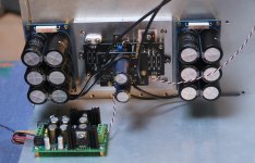
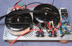
To start with a family photo.

Patrick
https://www.diyaudio.com/community/...a-zgf-headphone-amplifier.225577/post-7325913
This really have exceptional performace without applying any global negative feedback.
So why not a power amp version ?
For the last 2 years during Covid 19, we have been working quietly on a circlotron power buffer for loudspeakers.
It takes the same idea of the LU1014 Triode Cell from the Zen Variation 9, but is different in that the LU1014 is used in follower mode.
How that can be done, and how the challenges have been overcome, will be explained here.
To start with a family photo.
Patrick

First of all, there are quite a bit of circuit adaptations required to go from a headphone amp buffer to a speaker buffer.
These considerations and the required changes in the circuitry is discussed in the pdf attached.
Patrick
.
These considerations and the required changes in the circuitry is discussed in the pdf attached.
Patrick
.
Attachments
NicMac has done all the experimental work over the last 24 months.
I should leave him to give you details of his investigation, as well as the "final" build shown in post #1.
🤓
My most sincere thanks for the trust, and all the hard work that makes this into reality,
Patrick
I should leave him to give you details of his investigation, as well as the "final" build shown in post #1.
🤓
My most sincere thanks for the trust, and all the hard work that makes this into reality,
Patrick
Very exciting! Congrats! Looking forward to seeing more.
I have some LD1014's waiting for application to a worthy circuit and I've yet to try a circlotron.
I have some LD1014's waiting for application to a worthy circuit and I've yet to try a circlotron.
Great work Patrick!
I have 100 LU1014 in an envelope somewhere
Couple of questions:
power"
thd?
rail Vs? I just scan through the pdf quick.
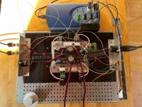
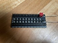
what are those comb-like things in the test rig pic?
best
I have 100 LU1014 in an envelope somewhere
Couple of questions:
power"
thd?
rail Vs? I just scan through the pdf quick.
what are those comb-like things in the test rig pic?
best
Fantastic write-up. Thank you for sharing. As always, I learn a lot. I keep all your articles for future reference as I learn a bit more. The 'bench work' for understanding the thermal compensation wasn't expected. I thought ... well, they'll just solve that with a servo or some other electronic trickery. Nope... another part stuck nearby on the sink. (If I understood correctly)...
Can't wait to see the work for tweaking performance.

Can't wait to see the work for tweaking performance.
very nice idea, I did a quick simulation on a Ludef ops and got 20x lower thd with a 0.37r resistor.
What value do you suggest as a maximum for this resistor?
A big thanks!
What value do you suggest as a maximum for this resistor?
A big thanks!
All the credit for this amp truly goes to Patrick. I have simply been fortunate enough to put it into practice and enhance its performance by conducting all the device-dependent experimental work that simulations cannot accomplish for you.
The amp lives up to my all my expectations in terms of sound and greatly exceeds them when it comes to measured performance. I have developed a fondness for the sound of my B-DAO head-amp and I had hoped that this new amp would offer a similar and equally impressive audio experience. Thankfully, it does. This similarity is not surprising, considering that the only significant difference between the two is the placement of a single resistor...
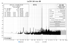
The amp operates silently with minimal noise (below 100 µV), and distortion is almost negligible (THD -100dB @ 1W into 8R). With the selected rails, the amp can deliver 30W into 8R, although I haven't extensively examined its clipping behavior as I do not have a pre-amp capable of providing the required voltage swing.
I have included an FFT plot for 1W into 8R, along with the unloaded loop-back measurement of the audio analyzer. These two measurements are remarkably similar, highlighting how close the amp is to the limitations of the measurement setup.
The amp lives up to my all my expectations in terms of sound and greatly exceeds them when it comes to measured performance. I have developed a fondness for the sound of my B-DAO head-amp and I had hoped that this new amp would offer a similar and equally impressive audio experience. Thankfully, it does. This similarity is not surprising, considering that the only significant difference between the two is the placement of a single resistor...
The amp operates silently with minimal noise (below 100 µV), and distortion is almost negligible (THD -100dB @ 1W into 8R). With the selected rails, the amp can deliver 30W into 8R, although I haven't extensively examined its clipping behavior as I do not have a pre-amp capable of providing the required voltage swing.
I have included an FFT plot for 1W into 8R, along with the unloaded loop-back measurement of the audio analyzer. These two measurements are remarkably similar, highlighting how close the amp is to the limitations of the measurement setup.
Attachments

The next days I will implement it in the ludef ops and measure it too.We measure.
I used the sim as a starting point. Even 2-3x lower thd is good for me.experimental work that simulations cannot accomplish for you
The LUDEF OPS is a completely different circuit.
I do not believe you can draw any parallel between our measured results here and that particular OPS.
You should really ask the designer of the other circuit what optimum resistor value should be used.
Not us. Simply because we cannot speak for someone else's design.
Cheers,
Patrick
I do not believe you can draw any parallel between our measured results here and that particular OPS.
You should really ask the designer of the other circuit what optimum resistor value should be used.
Not us. Simply because we cannot speak for someone else's design.
Cheers,
Patrick
Sorry for the off topic. I asked because they both use the cascoded lu1014 in the triode cell arrangement.
We have in the past been accused of being paranoid with our curve tracer matching.
But you can see in the distortion measurement posted above, especially how low second harmonics is.
This can only be achieved when you curve trace under operating conditions.
And then match to 3 coefficients in a 6th order polynomial of Id vs Vgs.
The 0th order, i.e. Vgs only ensures lowest DC offset.
The 1st order, i.e Ygs, ensures equal current sharing.
Only when the 2nd order coefficient is also identical that you will get perfect even harmonic cancellation.
As another example, TI said in one of their documents :
https://www.ti.com/lit/an/sloa054e/sloa054e.pdf
6. Reduced Even-Order Harmonic Distortion
Expanding the transfer functions of circuits into a power series is a typical way to quantify the distortion products.
Taking a generic expansion of the outputs and assuming matched amplifiers, we get:
Vout+ = k1Vin + k2Vin2 + k3Vin3 + . . . , and
Vout– = k1(–Vin)+ k2(–Vin)2 + k3(–Vin)3 + . . . . Taking the differential output
Vod = 2k1Vin + 2k3Vin3 + . . . , where k1, k2 and k3 are constants.
The quadratic terms gives rise to second-order harmonic distortion, the cubic terms gives rise to third-order harmonic distortion, and so on.
In a fully-differential amplifier, the odd-order terms retain their polarity, while the even-order terms are always positive.
When the differential is taken, the even order terms cancel. Real life is not quite this perfect.
Lab testing of the THS4141 at 1 MHz shows that the secondharmonic at the output is reduced by approximately 6 dB
when measured differentially as compared to measuring either output single-ended.
The third harmonic is unchanged between a differential and single-ended measurement.
So if you use a BB Chipamp in bridge mode, you only get 6dB H2 cancellation.
Unless you also measure and match them.
🤓
Cheers,
Patrick
Last edited:
I asked because they both use the cascoded lu1014 in the triode cell arrangement.
The IRF PMOS is part of the OPS and has its own signature which you cannot ignore.
Patrick
what are those comb-like things in the test rig pic?
Tired of repeatedly soldering and desoldering various combinations of low-value power resistors, I opted to create a straightforward, adjustable precision power resistor. This resistor consists of a series of 20 pieces of 0.05R resistors (0612, 1W, 1% tolerance). The resistance is adjusted using jumpers, employing two to reduce contact resistance. Consequently, the resistance can be set anywhere from 0 to 1R in 0.05R increments, with a nominally rated power of 1-20W depending on the chosen resistance.
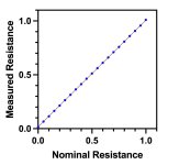
I constructed two of these resistors and verified their functionality by measuring the voltage drop across the resistor while maintaining a constant current of 0.5A. The measured resistance was consistently approximately 15mR higher than the nominal value, likely due to the resistance introduced by the jumpers. This additional resistance was found to remain relatively constant and unaffected by the set resistance value.
The variation in resistance between the two resistors across different settings was determined to be 0.12% with a tolerance of +/-0.21%.
Attachments

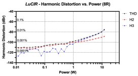
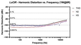
Here are a few additional measurements: THD versus power (4R and 8R) and THD versus frequency (8R). As expected, distortion slightly increases with higher power and frequency, but overall, it remains at a remarkably low level. The primary sources of distortion are H2 and H3, while higher-order harmonics have minimal impact.
It's important to note that this amplifier is not intended for individuals who are specifically concerned with "dominant negative phase H2" distortion. Instead, its strength lies in maintaining extremely low distortion across its entire operational range. This accomplishment is achieved by utilizing a minimal number of components, optimizing their performance, and operating the amplifier without global feedback.
It's important to note that this amplifier is not intended for individuals who are specifically concerned with "dominant negative phase H2" distortion. Instead, its strength lies in maintaining extremely low distortion across its entire operational range. This accomplishment is achieved by utilizing a minimal number of components, optimizing their performance, and operating the amplifier without global feedback.
Attachments

- Home
- Amplifiers
- Pass Labs
- The LU1014 Circlotron Power Buffer