The fourth entry is already in place.You know what they say about inputs. If you think you will need 3 you will need a 4th input the next day 🙂 Just kidding, most will be able to live with 3 inputs.
Please add M3 mounting holes. It will make installation simpler and the device will be more sturdy.
For M3 holes will be present and also the pads to the input capacitors smaller when my circuit pattern will be well ..
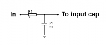
I'm doing this.Input filter is R first then C to GND...
It is good? 🙄
Attachments
Yes. To the volume control.... I would DC couple the filter to the volume control and then an input cap. Many manufacturers use also a cap in front of the volume control but 1 cap is better than 2 IMO. I don't know of input offset of the Kuartlotron topology. Input offset could cause the potentiometer to crackle that is why I think it is better to put the cap from the wiper to the Kuartlotron. Better ask Keantoken about this.
Last edited:
OK!I don't know of input offset of the Kuartlotron topology. Input offset could cause the potentiometer to crackle that is why I think it is better to put the cap from the wiper to the Kuartlotron. Better ask Keantoken about this.
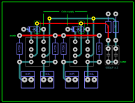
My picture is not very clear but the power runs relay will cross the tracks of the signal.
Avoid doing this or may be suitable?
Attachments
Both work, for smaller relays.I......................
Questions:
For the diodes on relays, 1N4148 appropriate or requires 1N4001?
.............
The input cable connects to the Hot pin of the filter and to the signal return side of the filter, (it is NOT ground).I'm doing this.
It is good? 🙄
The two outputs of the filter connects to the hot and cold inputs of the receiver circuit.
It's good but the filter still is wrong. First R then C. In the layout the C is from selected input rail (=output of relays) to GND and then follows a resistor to the volume control.
damn Murphy's Law! 🙁
Easy fix--just swap the capacitor and resistor locations.
As for RC values, I usually use 1000pF with a 1K resistor for a fc around 152KHz.
Some people prefer a higher cut-off frequency.
Great job so far Project!
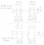
Hi Projet16, please allow me to propose a placement and routing scheme around the relays that seems to work cleanly. The sketch on the top uses the relays in your current layout. I saw you try not to run a trace between the relay pins but that probably has made things complicated. The least advanced PCB shops nowadays have no problems doing a trace in between 2.54mm DIP pins, so no point to avoid doing so.
The 2nd sketch uses a different relay that has 5mm pin spacing, not only can you run a trace in between the pins, you also have plenty room to wrap the signal traces with GND traces to cut down cross talk, if concerned.
In both sketches the signals are on one side of PCB, the other side of PCB can be a solid ground plane.
Attachments
Hello!
Ah Nattawa, I like these small relay! 😀
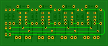
I made changes to the inputs and output so that there is no crossover tracks and I do not think I can do better.
Between the motorized potentiometer and the buffer it is possible to predict a thin sheet.
If you think it's okay, I continued with the supply establishment.
Regard's!
Ah Nattawa, I like these small relay! 😀
I made changes to the inputs and output so that there is no crossover tracks and I do not think I can do better.
Between the motorized potentiometer and the buffer it is possible to predict a thin sheet.
If you think it's okay, I continued with the supply establishment.
Regard's!
Attachments

Hi Project16,
I am not a skilled PCB designer so take my suggestion with caution or ignore if inappropriate.
So... I would move the input connectors closer together. You can even place them side by side. Then you you'll be able to flip down the input-to-ground 470k resistors away from relay flywheel diodes thus removing the long signal ground trace around. I would also use totally isolated relay switching lines and corresponding common return. May be it is planned so but it is not so clear from the PCB that you posted because the common return is not shown.
One more suggestion regarding the placement of the left and right channels. I would place them to the left and to the right of the potentiometer respectively. This will move the sensitive circuitry away from the motor. You can route the left input to the left from relays and the right input to the right since you have them anyways as parallel "bus" lines. The pos/neg regs can go in between the actual preamp and relays in an arrangement with let say positive supply to the right of the potentiometer and the negative to the left... Connect them together to make the common ground somewhere in between.
I hope my suggestions aren't totally off...
Regards,
Oleg
That should work.
In preamps they usually put the buffer after the pot so that the buffer buffers the load from affecting the operation of the pot, as well as the pot's variable impedance from affecting the operation of the equipment that follows. I'm not sure of the merits a pot trailing a buffer.
...and, the way the volume pot got wired up, is not backwards, is it? Or, am I looking at the wrong side of the board?
Thanks Nattawa, my mistake. I'm currently working on a buffer PCB myself which suppose to go AFTER the pot🙂 Somehow it did not even splash in my mind when I wrote the above post. But this would even further simplify the task of preamp placement.
Oleg
Oleg
Oleg,
Pick one of your inputs, draw on the route of the Signal getting in and through the relay contacts to the Receiver.
Then draw on the route of the Signal getting back out.
This Source to Receiver loop must have small LOOP AREA to minimise pickup of interference.
Pick one of your inputs, draw on the route of the Signal getting in and through the relay contacts to the Receiver.
Then draw on the route of the Signal getting back out.
This Source to Receiver loop must have small LOOP AREA to minimise pickup of interference.
Oops!
My potentiometer is not connected properly, it must be at the entrance of the buffer and not output. 😀
I take the route going!
My potentiometer is not connected properly, it must be at the entrance of the buffer and not output. 😀
I take the route going!
- Status
- Not open for further replies.
- Home
- Source & Line
- Analog Line Level
- The Kuartlotron - All in one layout conception