From the point of view of conventional EE added capacitor in question just introduces certain roll-of at upper limit of audio bandwidth. The claim is, beside roll-off, capacitor at this position makes staggering improvement of spacial quality of reproduced sound by activating some unknown mechanism.
One possible explanation is that this particular roll-off slope has some still unexplored psycho-acoustic effect that improves spacial perception. In that case the same effect should be achievable by introducing the same slope anywhere in the playback chain.
This can be confirmed (or dismissed) by proper A/B test with two identical DACs, where capacitor in question is added in one of them, and the same roll-off implemented on the other DAC but by adding RC on the output (matching of the slopes should be verified by measurements).
no there's potentially a lot more mechanisms at play here, but i'd have to see the circuitry details in order to make any pronouncements. there's grounding*and more importantly slew rate induced bandwidth limits due to pulsed current fast rise times. *grounding with larger caps on the wrong side of the tracks can cause IMD snafu's.
with PLLs this easy to measure due known sample rate spurs and PM noise shaping at cutoff. I reckon decoded swept single tones on audio circuits would be similar.
I didn't consider that but you maybe right, since the OP says nirvana is also achieved in the preamp side. although it would pure chance if the same cutoff frequency was achieved simply moving a cap around randomly tho. easy to calculate-n-measure with the details provided.
with PLLs this easy to measure due known sample rate spurs and PM noise shaping at cutoff. I reckon decoded swept single tones on audio circuits would be similar.
One possible explanation is that this particular roll-off slope has some still unexplored psycho-acoustic effect that improves spacial perception. In that case the same effect should be achievable by introducing the same slope anywhere in the playback chain.
I didn't consider that but you maybe right, since the OP says nirvana is also achieved in the preamp side. although it would pure chance if the same cutoff frequency was achieved simply moving a cap around randomly tho. easy to calculate-n-measure with the details provided.
Last edited:
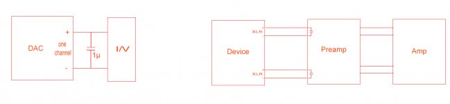
This is the schematic for placement of this cap in two different situations. If used in the both positions in the same chain, it seems to improve the effect even more, and it allow somehow to control the soundstage space, or "shape", or so (see my first post for descriptions).
For me it works in a appropriate way, on DAC using this 1µ cap. Just pure and simple placed so over the +/- lines. In preamp is a different C value, but identical and similar placed for both channels.
The cap value is to be experimental established, because is function of the device configuration, as many other variables from case to case.
On DAC I could detect this effect when using very different values, started with few hundreds pF, and ended with this 1µ, which I appreciate it as giving me a right space/effect on the soundscene.
One may note that the presence of this cap it have not so ever influence on the signal`s high fidelity, but the only audible effect is when about the soundscene, and the precision of the sound elements positions in it. While without this cap in place the positions of the sound elements can be located on the two speakers locations, in centre and quite difuse in between centre and one or another of the speakers, with this cap in place, the locations of the sound elements become more accurate, precise and even better placed in space (far/near). Just amazing it become this soundscene when it consist of moving sound elements.
Attachments
Last edited:
Coris, can you measure (and compare) frequency response when effect is established by cap in DAC and when it is done in preamp? How many dB down you get at 20kHz in both cases?
It has always been called a pre-filter in the EE comms community.
Yes simple circuit changes sometimes have big implications ( specially true at digital to analog interfaces in my experience ), so not sure why this rules out being a called pre-filter by you?
I never wrote that the effect rules out any naming convention. However, simply calling it a pre-filter carries the conotation of a bandwidth limiting primary function. When positioned at the output of a DAC, a pre-filter is typically intended to suppress the level of RF applied to succeeding active filters. That doesn't appear to be the primary benefit of Joe's suggested filter repsonse.
I know the mechanisms it prevents, but don't bother waxing about the sound perceptions, I'll leave that to the 'Poets of Audio' designers community.
It's condescending langauge like that which plagued open discussion this topic in the prior thread.
BTW it really doesn't make sense to talk of such things without a schematic in hand, I reckon it's a mistake in earlier DAC I/V converters.
Joe Rasmussen has tirelessly provided many such schematics before on this forum. They are easily found.
Has ANYONE been able to demonstrate the existence of this alleged "effect"?
SY, I've demonstrated it to myself when I was quite skeptical beforehand. If I hadn't respect for Joe's prior work I might have dismissed it as pure snakeoil and not bothered to try it.
No, my demonstration was not double-blind. This is DIY afterall, where most reports will be of an anecdotal hobbyist nature and lacking scientific rigor. In the meanwhile, it is very easy to conduct one's own debunking listening experiment. 🙂
Last edited:
So in order for me to take part in a discussion about whether there are fairies at the bottom of gardens it is necessary for me personally to experience a fairy?
Jeez, man. We're talking about an acoustical perception effect, not magical beings.
I can't use classical mechanics to calculate the flight of a thrown ball under gravity (and inertia) unless I have thrown a ball?
How productive, do you suppose, would be a dicussion to explore the cause of gravity and inertial effects if one side of the discussion had not or did not observe or accept the reality of those effects?
The previous thread on this subject ran into the sand because attempts to be awkward and apply circuit theory (albeit perhaps somewhat lesser known circuit theory, such as the impedance of a virtual ground) were brushed aside as irrelevant. When circuit theory is regarded as irrelevant to a discussion about circuits then little progress can be made.
When someone reports an unexpected phenomenon one of the plausibility tests which should be used is "does existing theory, carefully applied, explain the claimed phenomenon or rule it out or leave it as an open question?" This may not satisfy those who want to establish not just a new phenomenon but also a new theory to explain it. Unfortunately, in electronics there can be no new theories - we are stuck with the low frequency approximation of electromagnetism (otherwise known as circuit theory).
I don't recall circuit theory being pushed aside in the prior thread. I do recall certain circuit theories not simply being accepted as the only possible explanation, usually because they didn't appear to fully fit the observed behavior of the phenomena.
By the way, there seems to be the disturbing assumption by a certain few here that only that certain few have had benefit of a classical engineering education, and that most everyone else is either a charlatan, a dilatante, or a fool. This is unfortunate.
Last edited:
The simplest explanation is that the standard parts don't work quite well enough to match what normal explanations would have us believe is the full story, especially in dynamic use, that is, replaying music. Just enough for the ear to pick that something is going on. DAC chips fit that category beautifully; they are not "perfect", not by a long shot. Which means changing the conditions in their vicinity will change the sound - the precise understanding of the particular mechanism may be very difficult, because that would entail an extremely detailed knowledge of the internals of the chip, something they're not willing to give us ... 🙂.
all wrong assumptions. a cap across a DACs output forms a simple RC filter. So a pre filter works to slow the DACs step change in the time domain, not by filtering "RF". when the op-amps input sees a fast digital pulse, faster than it can respond to it goes into slew rate limit or large signal response. Since active filters depend on an op-amps small signal parameters they tend to fall apart in the AF band when that happens. old reference here please read it. this is called slew rate limiting. too bad Millman didn't call it his effect. 🙂 http://www.ti.com/lit/an/snoa852/snoa852.pdfI never wrote that the effect rules out any naming convention. However, simply calling it a pre-filter carries the conotation of a bandwidth limiting primary function. When positioned at the output of a DAC, a pre-filter is typically intended to suppress the level of RF applied to succeeding active filters. That doesn't appear to be the primary benefit of Joe's suggested filter response.
what can I say, if like the hat, you can wear it too.🙂 Just because yer unaware of something doesn't mean you get to name it after some part tweeker dude. believe me there is prior art here... way before you guys. if anyone is being pretentious and ignorant at the same time... a terribly sad combination IMO.It's condescending langauge like that which plagued open discussion this topic in the prior thread.
Last edited:
Could the capacitor/resistor be an impedance correction for the current sources (iout) of the DAC? Like a zobel used to correct the impedance of a speaker driver.
An analogue solution for an analogue problem.
An analogue solution for an analogue problem.
Coris, can you measure (and compare) frequency response when effect is established by cap in DAC and when it is done in preamp? How many dB down you get at 20kHz in both cases?
Well, not just easy task to do it in my particular case, but I will try it one day...
The DAC I use this effect for is included in a whole device, difficult enough to isolate it and measure it in details.
In my experiments I have measured the DAC device XLR outputs levels in two situations, using two cap values on the DAC output channels: 1µ, and 2µ.
Here are the results:
C1µ
1khz - 6,11Vpp
20Khz - 4,90Vpp
40khz - 4,94Vpp
80khz - 5,35Vpp
C2µ
1khz - 6,11Vpp
20khz - 4,90Vpp
40khz - 5,11Vpp
80khz - 6,03Vpp
SY, I've demonstrated it to myself when I was quite skeptical beforehand. ...
No, my demonstration was not double-blind.
OK, so the answer is apparently, "No, no-one has been able to actually demonstrate the existence of the alleged 'effect'." So, indeed, the evidence is of the same quality as that supporting alien abductions with anal probing or fairies in the garden.
.............. alien abductions with anal probing ............
This is indeed a very interesting expression... At least it fit very well in the thread subject...
Thanks for your always interesting contributions to this discussion.
When positioned at the output of a DAC, a pre-filter is typically intended to suppress the level of RF applied to succeeding active filters. That doesn't appear to be the primary benefit of Joe's suggested filter repsonse.
My problem with the last thread was that this was not proven with any engineering rigor. We did this in 1991 on a datasheet with an AD1862 DAC, the RFI suppression was measured with a broadband spectrum analyzer and it was considerable. As people have mentioned op-amps especially vintage ones like 5532's have an inductive output impedance at high frequencies and using the integrating filter capacitor across the I/V resistor fails at high frequency.
No experiment has been proposed so far that eliminates this and isolates the simple BW limiting, though I have to admit I've lost track of exactly what is being claimed.
Excellent, then perhaps you'll do the first step, which is to confirm the existence of the 'effect' (or perhaps find that it isn't actually audible, at least to you). I'm continually surprised at the lack of intellectual curiosity that keeps people from doing basic ears-only experiments before running off on tangents. I am encouraged that you seem to be a bit more open-minded; I will be interested to see your results.
You seem to be equating "conventional EE" to 'naive EE'. Yes a cap will add a filter, but not necessarily just a pure HF rolloff. The "unknown mechanism" may just be 'not that well known'. Let us be clear: whatever the effect (if it is real - and that still has to be determined) it can be explained using circuit theory. No new physics will be needed.chip_mk said:From the point of view of conventional EE added capacitor in question just introduces certain roll-of at upper limit of audio bandwidth. The claim is, beside roll-off, capacitor at this position makes staggering improvement of spacial quality of reproduced sound by activating some unknown mechanism.
Therefore a good line of approach is to carefully consider what a cap at that position could do. For example, how will it interact with the impedance which would be seen at that point in the absence of the extra cap?
The electrical effect of adding a capacitor to a circuit should not be a matter of dispute, except where there are aspects of the circuit which are not immediately obvious. Even then, all people with sufficient knowledge of circuits should eventually converge on the true explanation. You said that people can't contribute unless they have heard the effect; this is daft. I can, at least in principle, calculate the effects of gravity around a black hole but I have never (to my knowledge) experienced a black hole nor wish to do so. You are mixing two quite different issues: what is the circuit doing vs. how does it sound. I don't attempt to comment on how it sounds, but I can use circuit theory to explore the circuit.Ken Newton said:How productive, do you suppose, would be a dicussion to explore the cause of gravity and inertial effects if one side of the discussion had not or did not observe or accept the reality of those effects?
Joe put up some circuits which he said exhibited the effect, and claimed that this was unexpected/unexplained. Like any good physicist I picked the simplest circuit (opamp virtual ground) and began to show that this could have effects which some might find unexpected. Joe then tried to withdraw that circuit from the discussion. My impression was that he didn't really want an explanation, as that would dissipate the 'magic'.I don't recall circuit theory being pushed aside in the prior thread.
I never got an explanation from him how he produced his graphs. If they were measurements then they were open to all sorts of experimental error, as all such things are. If they were simulations then the explanation for them must lie in the models used.
I think there is a disturbing assumption by a certain few here that only that certain few have the ears and systems with sufficient discrimination to hear this effect; only the certain few have the deep knowledge to really investigate this - everyone else is merely trying to use 'conventional' knowledge to explain something very deep and esoteric. This is counterproductive, as it suggests that, deep down, they don't really want an explanation - at least, not one based on physics.By the way, there seems to be the disturbing assumption by a certain few here that only that certain few have had benefit of a classical engineering education, and that most everyone else is either a charlatan, a dilatante, or a fool. This is unfortunate.
My own view is that if there is an effect (and I am not convinced) then it is either a mild filtering of audio (which can be unexpectedly audible) or a significant filtering of ultrasonics (so reducing IM etc. due to slew rate problems in whatever comes next). It has been suggested that it is something to do with the details of DAC output stages, but this is most unlikely as the effect is said to be present with both current and voltage output chips - but these would have very different output stage topologies.
Coris, only undisputed change this capacitor introduce is a change in the frequency response. All other possibilities are just conjectures at the moment.
It seems the only way to verify existence of the effect is to do A/B comparison of a DAC modified to show the effect with a reference DAC.
- You need two identical DACs
- One should be modified with Joe’s capacitor and subjectively show the effect
- The other should have an ordinary low pass filter implemented in some other position in the circuit to match the frequency response of the modified DAC
- Find 10 or more experienced listeners and let them A/B compare these two DACs. Let them vote which DAC has better spatial presentation.
If results show no preference, the effect is either nonexistent or is based in psychoacoustics.
If results show clear preference the next step to do is to search for low level difference in measured performance of the two DACs (compare impulse response, IMD spectrum, etc).
all wrong assumptions.
A convienent declaration without any proof provided.
a cap across a DACs output forms a simple RC filter.
No, not necessarily. Many DAC feature active current source outputs, so, no simple R. In addition, the output impedance is usually code dependant, so it changes dynamically with the signal, often exhibiting a code dependant shunt capacitance as well. Furthermore, feedback based active I/V circuits usually become inductive at high frequencies, so the load is not necessarily simple either.
So a pre filter works to slow the DACs step change in the time domain, not by filtering "RF". when the op-amps input sees a fast digital pulse, faster than it can respond to it goes into slew rate limit or large signal response.
Again, no, not necessarily so simple. RF could provoke rectification by the input stage. So, it's not only a matter of slew rate limiting, although I'd agree that is the primary concern. I perhaps too casually used the term RF when generally referring to factors which challenge the A.C. performance of an active gain stage. I was posting, not writing a textbook. Seriously, you are straining too hard to find grounds for a fight. Not a good choice on your part.
Since active filters depend on an op-amps small signal parameters they tend to fall apart in the AF band when that happens. old reference here please read it. this is called slew rate limiting. too bad Millman didn't call it his effect. 🙂 http://www.ti.com/lit/an/snoa852/snoa852.pdf
Yet more arrogant assumptions by you. Not only am I well aware of the large signal consequences of when an op-amps run out of GBWP, I'll venture to suggest that most participants on this forum are well aware of this issue.
what can I say, if like the hat, you can wear it too.🙂 Just because yer unaware of something doesn't mean you get to name it after some part tweeker dude. believe me there is prior art here... way before you guys. if anyone is being pretentious and ignorant at the same time... a terribly sad combination IMO.
Yes, that statement exposes the root of the matter, I think. Your sensibilities (or is that your ego?) are offended by the naming of an observed effect, not in a peer reviewed paper, but on a forum thread? Really? You perjoratively refer to Joe Rasmussen as "some parts tweeker dude", when I'd wager a fair sum that Joe has made by far more constructive contributions to this field than you. We do agree on one thing, it is terribly sad, just not for the reasons that you see.
Last edited:
Coris, only undisputed change this capacitor introduce is a change in the frequency response. All other possibilities are just conjectures at the moment.
It seems the only way to verify existence of the effect is to do A/B comparison of a DAC modified to show the effect with a reference DAC.
- You need two identical DACs
- One should be modified with Joe’s capacitor and subjectively show the effect
- The other should have an ordinary low pass filter implemented in some other position in the circuit to match the frequency response of the modified DAC
- Find 10 or more experienced listeners and let them A/B compare these two DACs. Let them vote which DAC has better spatial presentation.
If results show no preference, the effect is either nonexistent or is based in psychoacoustics.
If results show clear preference the next step to do is to search for low level difference in measured performance of the two DACs (compare impulse response, IMD spectrum, etc).
Thanks for suggestions. Some of it are quite difficult to follow, but I will try to find ways to get more infos out of this approach...
In the mean while if it may be convenient for you, maybe you will try to solder these two caps into your device, to observe what happen.
Really, you don't need 10 listeners, only one who believes that he hears the effect. An ears-only comparison is simple to set up and run. The results won't be universal, they'll only apply to the one listener, but if positive, it demonstrates the reality of the purported effect. If negative, it will (we hope) inspire a few others who believe they hear it to try the same experiment.
- Status
- Not open for further replies.
- Home
- Member Areas
- The Lounge
- The Joe`s capacitor...