The problem with measuring W&F using a test LP is it can be difficult to tell what is caused by the turntable drive/platter and what is caused by artifacts in the playback chain.
Measuring the FG like JP did removes all external forces measuring only drive stability.
For a platter to increase W&F in a DD TT the most likely cause is increased vertical or horizontal runout caused by the surfaces not being machined to close enough tolerance or out of balance adding additional side load to the bearing. Also the TT needs to be leveled more accurately as the additional mass can top effect and cause wobble in the bearing.
I have measured platter vertical runout of multiple platters (3x OEM, SS and GM) connected to one of my SP10 motors. I can clearly see inconsistent rotation. The cause is hydraulic hammering in the bearing. The bearing is a hydrodynamic unit and even though the clearance is minimal approx 0.03mm this causes the spindle to rotate eccentric resulting in high and low pressure areas between the spindle and sleeve as the spindle rotates. This hammering shows up as a pulsing on the dial indicator as the platter rotates.
My experience is different. Regardless, if we can get some proper measurements it can be proven out, one way or the other.
Sadly, the Ultimate Analogue Test LP never misses a chance to disappoint.
I reported my previous disappointment in the Ultimate Analogue Test LP four years ago. It really is not fit for purpose in so many regards
https://www.diyaudio.com/forums/ana...-test-lp-aapt-1-vs-hfn-001-a.html#post4971923.
However it is all I have available for W&F testing.
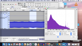
Regardless, the Delrin/SS sample shows a lot of AM in the recording, and though due to the test record used no conclusions can be drawn, I see indications of very uneven rotation in the polar plot, around 40deg to 95deg.
Image order is Delrin/SS, 10R, and my 10R for reference.
I would expect my stock 10R performs very close to yours.
This was the reason I included it. The fact that it does not points the finger clearly at the test LP. Arguably the W&F results for my 10R are as bad as the Delrin/SS which is unlikely.
The AM modulation is clearly apparent in the polar plots. I count approximately 21 peaks in the polar plot which corresponds to an AM frequency of 11.7 Hz, close to the cartridge/tonearm lateral resonance modulation frequency I reported from post #1713. The tonearm can be clearly seen swinging laterally during the tests because of the off centre LP. This will excite the lateral AM modulation seen in the plots.
I was informed 'that a South African chap (Shaun Vervacht) had carried out tests on Increased Weight to a Platter on a SP10 MKII, and that there were findings that flutter will increase'.
Is it this member?
https://www.diyaudio.com/forums/ana...0-mod-plinth-la-kaneta-ideas.html#post1114902
If he is still around maybe he can comment.
The problem with measuring W&F using a test LP is it can be difficult to tell what is caused by the turntable drive/platter and what is caused by artifacts in the playback chain.
I am going to go through this massive thread.🙁
Turntable speed stabilty
Luckythedog seems to have good insight into the mechanical aspects of turntable speed stability and measurement.
The AM modulation is clearly apparent in the polar plots. I count approximately 21 peaks in the polar plot which corresponds to an AM frequency of 11.7 Hz, close to the cartridge/tonearm lateral resonance modulation frequency I reported from post #1713. The tonearm can be clearly seen swinging laterally during the tests because of the off centre LP. This will excite the lateral AM modulation seen in the plots.
I don't see how an off-centre LP is going to excite an 11Hz cartridge resonance, and it wouldn't manifest so drastically. Seems little point in trying to draw any conclusions at all until a good W&F track is used and the test files are of a reasonable sample rate as there could be artifacts from that conversion.
I would expect my stock 10R performs very close to yours.
This was the reason I included it. The fact that it does not points the finger clearly at the test LP. Arguably the W&F results for my 10R are as bad as the Delrin/SS which is unlikely.
The AM modulation is clearly apparent in the polar plots. I count approximately 21 peaks in the polar plot which corresponds to an AM frequency of 11.7 Hz, close to the cartridge/tonearm lateral resonance modulation frequency I reported from post #1713.
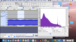
I repeated the Kaneta plinth W&F tests with the Delrin/SS platter and also the OEM platter, despite the misgivings about the Ultimate Analogue Test LP. The plots are First Delrin/SS, second OEM. The same AM is evident, which shows the artefact is not caused by the Delrin/SS platter.
I suspect that the polar plots will be similar as well, which if true, would be more evidence against the test LP's usefulness.
Attachments
@ JPI suspect that the polar plots will be similar as well ...
You are correct, the polar plots do not show not AM. I misspoke. The Audacity plots do.
Is it this member?
https://www.diyaudio.com/forums/ana...0-mod-plinth-la-kaneta-ideas.html#post1114902
If he is still around maybe he can comment.
I had discovered the Historical Thread after posting.
I ran through the thread but did not see the information about the test on increased platter weight.
From the positive reports being made about the New Platters SQ, there will be a growing interest,
I have seen SP10 SS Platters in use in Japan, and I also know of other productions made available in the past.
Last edited:
However amplitude modulation is frequency modulation with an upper and a lower sideband.@ JP
You are correct, the polar plots do not show not AM.
Using amplitude modulation to find the frequency content of the modulated signal? | Yahoo Answers
The simple trigonometric calculations show that an ideal sine wave carrier that is amplitude modulated by an ideal low frequency sine wave, is the sum of the carrier plus two sidebands equally offset in frequency to the carrier.
Shown separately on a polar plot, the ideal carrier and 2 sidebands would each describe a circle at slightly differing radius, carrier in the middle. The combined signal polar plot would wiggle between the 2 outer sideband circles.
To a first order, what can be seen in the plot in post #1727, are 3.15 kHz plots with an 11-12 Hz amplitude modulation. A spectrum analyser with sufficiently high resolution would show the typical central peak at 3.15 kHz plus 2 sidebands offset at ±11 Hz.
Last edited:
I was informed 'that a South African chap (Shaun Vervacht) had carried out tests on Increased Weight to a Platter on a SP10 MKII, and that there were findings that flutter will increase'.
Not guilty! It was @Steerpike. You'll find his efforts here: "SP10 Motor Controller Specification".
I was exploring the possibility of making my own SP10 motor controller. However, Steerpike did appear to have better knowledge and experience, so I deferred to him and his subsequent project. IIRC, he was developing the controller using more readily-available components. I believe that part of his design process was to evaluate how mass affects system stability/speed regulation. In principle, the SP10 FG circuit is designed to control the specific platter mass. The motor driver, motor and its load (platter mass) have a unique dynamic characteristic. If one of these factors is changed, there is a high probability that performance will suffer. In conclusion, changing the platter mass would require the control loop to be re-tuned - not a trivial exercise. I suspect that it is the latter factor that is to blame for Steerpike's project being unfinished.
FYI: I stopped monitoring this thread recently, as I no longer have SP10 parts and have since disposed of the bulk of my record collection. My current turntable is a very humble Aiwa AP-2200!

In principle, the SP10 FG circuit is designed to control the specific platter mass. The motor driver, motor and its load (platter mass) have a unique dynamic characteristic. If one of these factors is changed, there is a high probability that performance will suffer. In conclusion, changing the platter mass would require the control loop to be re-tuned - not a trivial exercise. I suspect that it is the latter factor that is to blame for Steerpike's project being unfinished.
It's not platter mass that effects the PLL is Moment of Inertia. I have measured the PLL circuit with an 8kg platter and PLL stability is unaffected by the increased mass.
Decreasing MoI will have a greater impact on rotational stability. Obviously increasing mass to the point the motor has insufficient torque would effect rotational stability, but the SP10mk2 will spin up an 8kg platter to 33rpm in less than 1 revolution.
Period S & T, changing platters didn't require adjustment. Once I have my new Kaneta plinth completed I will measure the FG signal under load, ie playing an LP, it's not possible to do this with my current TT.
- Home
- Source & Line
- Analogue Source
- The Incredible Technics SP-10 Thread