Do I need a scope for recapping?
Not that I am against it, but it is way out of my budget right now... Still need to save some money to buy an arm 🙂. It is not going to play music without it 🙂)
Not that I am against it, but it is way out of my budget right now... Still need to save some money to buy an arm 🙂. It is not going to play music without it 🙂)
Just to confirm, the strobe and motor drive is perfect. I would do no more now.
X1 looks good and original. The layout is original too.
No point in a re-cap if all is perfect. But as said above, use the same value, maybe the next voltage rating up and Panasonic FC, but honestly, why bother ? The caps used in the SP-10 are good, unlike the RS-1500 where all 100+ need to be replaced.
If you do re-cap it is essential to set it up afterwards with a scope, otherwise it will probably be worse than when you started. Re-capping is no magic cure, often quite the reverse.
Dave
Finished the recap of the power supply. Short version, all went well and voltages only needed a little adjustment.
This and the table has been recapped before. The job was not done very well and they used some Nichicon Muse Bi-Polar caps. From what I've read this is a no-no if Polar caps are required. They also left the large can cap behind the faceplate and tie-wrapped another to the side of it. Just kind of shoddy work.
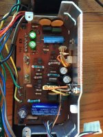
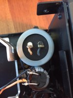
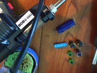
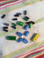
So to keep myself organized I laid out all the new caps
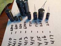
On a previous project I bought Hakko 808 desoldering gun. Makes quick work of removing the caps.
And back in.
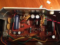
This and the table has been recapped before. The job was not done very well and they used some Nichicon Muse Bi-Polar caps. From what I've read this is a no-no if Polar caps are required. They also left the large can cap behind the faceplate and tie-wrapped another to the side of it. Just kind of shoddy work.


So to keep myself organized I laid out all the new caps

On a previous project I bought Hakko 808 desoldering gun. Makes quick work of removing the caps.

And back in.

Technics SP-10 capacitors

Before as above

After as above
OK, time zones are zapping me !
I thought I would elaborate on why I asked to see the motor drive on A1, A2, & A3.
Apart from the PSU I have never seen a single capacitor failure on a SP-10 apart from C2, C4 & C6 on the Drive Circuit PCB. Here are before and after results when they do fail, usually after 20 years of 24/7/365 in broadcast studios.
I use the Panasonic FC 10uF 100V, Mouser part number FC 667-EEU-FC2A100.
BTW, I have had zenners fail in the PSU, but the best thing to do with the PSU is to bin it and start again, changing all the capacitors, diodes and zenners is a bridge too far for me.
Regards
Dave

Before as above

After as above
OK, time zones are zapping me !
I thought I would elaborate on why I asked to see the motor drive on A1, A2, & A3.
Apart from the PSU I have never seen a single capacitor failure on a SP-10 apart from C2, C4 & C6 on the Drive Circuit PCB. Here are before and after results when they do fail, usually after 20 years of 24/7/365 in broadcast studios.
I use the Panasonic FC 10uF 100V, Mouser part number FC 667-EEU-FC2A100.
BTW, I have had zenners fail in the PSU, but the best thing to do with the PSU is to bin it and start again, changing all the capacitors, diodes and zenners is a bridge too far for me.
Regards
Dave
Last edited:
So I am going to lubricate the table, do you think I just should put couple of drops into that hole, or take everything apart, clean and lubricate? From what I understand SAE 20 engine oil is the same iso68 Technics recommend, right?
Just put a few drops down the lube hole. If and when you replace the bearing cap and ball, take it apart then.
That was the point to take it apart to check how worn is the cap. I just can't understand how to pull the spindle from the motor... do I need to unscrew something?
Thanks! Sorry for being that annoying. I see how people explaining how to unscrew that bottom cup to get to the ball, but how to pull out the shaft. I am either missing it somewhere or... well, most likely missing 🙂
Today I replaced all the recommended caps under the table, fixed a couple errors, one by Technics, one by a previous owner/tech.
I also serviced the bearing, and replaced the thrust pad.
After this phase of work I hooked it back up to the scope. Even though I had just set it, changing the caps required both VR's to be adjusted. This shows for sure that changing the caps requires a scope.
This work today took me about 5 hours, as a reference. I'm just a beginner so my process could be flawed or outright wrong, but everything works and was able to adjust correctly. That being said, here is what I have learned and what I did.
Pulling the platter, brake, covers and circuit boards are pretty straight forward and did not present a challenge. Before I pulled the screws that held the motor I removed the bearing cap. I put a line with a marker between the cap and the motor base for alignment later. I used my heat gun circling around the cap for about 4 minutes before the thread locker was loose enough so that I could twist off cap by hand, with a dish rag. The cap twists off counterclockwise as you would expect.
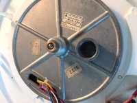
Then I flipped the table over and pulled the sub platter/rotor? out of the bearing shaft. This of course after I removed the aluminum retaining plate. This exposes the thrust pad that is on the bottom of the spindle. Then using a bamboo based chopstick (from the silverware drawer), and my homeowner picture hanging hammer I tapped out the ball bearing, 1 medium swat. I used a socket about the size of the outside diameter of the bearing shaft to support the bearing for the swat. Also worked good to catch the ball bearing!
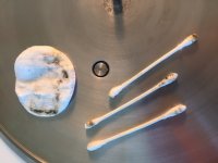
I don't believe the bearing has ever been serviced. Very dirty and the thrust pad had a decent size dimple. I used a mixture of 25% alcohol with water, a few Q-tips and one of my wife's makeup removing pads. The shaft showed some wear markings, but my novice eye didn't pick up an issue.
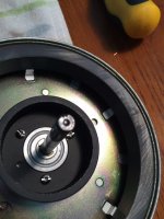
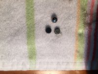
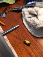
Then a fine coat of oil on the parts that touch and pushed on the thrust pad. I used the synthetic oil I posted previously. BTW, a quick flick with a knife blade gets the old thrust pad off the shaft.
I followed the lead of an other DIY'er on how to reinstall the ball bearing. After everything was cleaned and oiled I placed the ball bearing on the opening of the shaft. I located it at about 45* off from where it had been before, you could still see a faint black line where it had been. This way the thrust pad and the bottom cup would see new steel.
Then carefully screwed the cap back on, and in turn, pushed the ball bearing back into the shaft. Note, I did not remove the thread locker or clean the threads. I heated the cup back up and twisted it as tight as I could by hand, with a rag. Leaving the original thread locker to continue to keep everything locked. As you can see in the pic I actually turned it a tad bit more than previous. This way I know the ball bearing is tight to the shaft and the bottom of the cup. Since I will be installing a bearing drain I know everything will be connected.
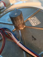
The rest of the assembly in the reverse of disassembly, no surprises.
I also replaced all the recommended caps. I followed the list I posted earlier. I can't tell you how nice it is to have a good solder sucker! Just hold it over the lead and tight to the solder till it starts to melt, hit the trigger, and the parts just about fall off! And with minimal aggravation on the traces I didn't have one lift. Other than issues by the previous hack.
I found one leg of a resistor that I don't think was ever soldered by Technics. The board in this are shows some blackening. I also had to fix/redo the installation of X1, Oscillator. It had been installed on the bottom of the board and looks like it had been hit and the traces were lifting. I moved to the right side of the board and bypassed the traces.
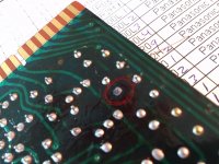
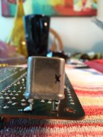
After the recap and repairs I cleaned the backside of all the boards with 25* alcohol and a toothbrush. Then rinsed with clean water with the toothbrush and dapped dry with a microfiber rag.

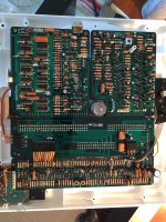
I used my variac to slowly power it back up, no magic smoke and everything was lighting up and the speed all worked.
Then on to the scope. Adjusted back to spec.
Just listened to two albums, might be my imagination, but sounds richer and more depth.
I also serviced the bearing, and replaced the thrust pad.
After this phase of work I hooked it back up to the scope. Even though I had just set it, changing the caps required both VR's to be adjusted. This shows for sure that changing the caps requires a scope.
This work today took me about 5 hours, as a reference. I'm just a beginner so my process could be flawed or outright wrong, but everything works and was able to adjust correctly. That being said, here is what I have learned and what I did.
Pulling the platter, brake, covers and circuit boards are pretty straight forward and did not present a challenge. Before I pulled the screws that held the motor I removed the bearing cap. I put a line with a marker between the cap and the motor base for alignment later. I used my heat gun circling around the cap for about 4 minutes before the thread locker was loose enough so that I could twist off cap by hand, with a dish rag. The cap twists off counterclockwise as you would expect.

Then I flipped the table over and pulled the sub platter/rotor? out of the bearing shaft. This of course after I removed the aluminum retaining plate. This exposes the thrust pad that is on the bottom of the spindle. Then using a bamboo based chopstick (from the silverware drawer), and my homeowner picture hanging hammer I tapped out the ball bearing, 1 medium swat. I used a socket about the size of the outside diameter of the bearing shaft to support the bearing for the swat. Also worked good to catch the ball bearing!
I don't believe the bearing has ever been serviced. Very dirty and the thrust pad had a decent size dimple. I used a mixture of 25% alcohol with water, a few Q-tips and one of my wife's makeup removing pads. The shaft showed some wear markings, but my novice eye didn't pick up an issue.


Then a fine coat of oil on the parts that touch and pushed on the thrust pad. I used the synthetic oil I posted previously. BTW, a quick flick with a knife blade gets the old thrust pad off the shaft.
I followed the lead of an other DIY'er on how to reinstall the ball bearing. After everything was cleaned and oiled I placed the ball bearing on the opening of the shaft. I located it at about 45* off from where it had been before, you could still see a faint black line where it had been. This way the thrust pad and the bottom cup would see new steel.
Then carefully screwed the cap back on, and in turn, pushed the ball bearing back into the shaft. Note, I did not remove the thread locker or clean the threads. I heated the cup back up and twisted it as tight as I could by hand, with a rag. Leaving the original thread locker to continue to keep everything locked. As you can see in the pic I actually turned it a tad bit more than previous. This way I know the ball bearing is tight to the shaft and the bottom of the cup. Since I will be installing a bearing drain I know everything will be connected.

The rest of the assembly in the reverse of disassembly, no surprises.
I also replaced all the recommended caps. I followed the list I posted earlier. I can't tell you how nice it is to have a good solder sucker! Just hold it over the lead and tight to the solder till it starts to melt, hit the trigger, and the parts just about fall off! And with minimal aggravation on the traces I didn't have one lift. Other than issues by the previous hack.
I found one leg of a resistor that I don't think was ever soldered by Technics. The board in this are shows some blackening. I also had to fix/redo the installation of X1, Oscillator. It had been installed on the bottom of the board and looks like it had been hit and the traces were lifting. I moved to the right side of the board and bypassed the traces.


After the recap and repairs I cleaned the backside of all the boards with 25* alcohol and a toothbrush. Then rinsed with clean water with the toothbrush and dapped dry with a microfiber rag.


I used my variac to slowly power it back up, no magic smoke and everything was lighting up and the speed all worked.
Then on to the scope. Adjusted back to spec.
Just listened to two albums, might be my imagination, but sounds richer and more depth.
Last edited:
Thank you for sharing! This is very, very useful!
Just did a little editing while you were posting. Sorry I didn't get this done just a little earlier to answer more of your questions. 😉
This thread started by Jim must be the best SP-10 resource ever !
Has anyone made a new thrust pad or looked at it ?
Dave
Has anyone made a new thrust pad or looked at it ?
Dave
Here is a pic of just how dirty the shaft, bearing, spindle were. Forgot to add earlier. Just shows that this area of the turntable needs to be timely serviced.
View attachment 455953
Is that the rod cup on the tight and the pad on the left (picture where the on the towel with the ball in the middle)? As I understand this is the pad Dave is asking and it is located under the ball in that cup you unscrew? It doesn't look worn right?
Has anyone made a new thrust pad or looked at it ?
Yes.
User510 has done an awful lot on this front - sp10 brg
Link to pads for sale - sp10mkII_pad
I have one for each of my tables (and a new SiN ball). jpjones has installed the new pad on his. (see post #69 this thread)
Other cool stuff worth looking at -
Bearing wear on an SP 10 mk II PICS - AudioKarma.org Home Audio Stereo Discussion Forums
sp10_Mule
Is that the rod cup on the tight and the pad on the left (picture where the on the towel with the ball in the middle)? As I understand this is the pad Dave is asking and it is located under the ball in that cup you unscrew? It doesn't look worn right?
I bought mine from Steve also (user510) made from Torlon 301. $35 with free shipping.
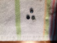
In the pic the piece on the bottom left is the new pad, the ball bearing in the middle top and the worn pad on the bottom right. The amount of wear is the size of the dimple. The dimple on mine is not as bad as some I've seen posted, but a lot more it it should.
Read all the work that was done to get these new pads to market, follow the links 6L6 posted.
Technics SP-10 Mk2A, a project by 6L6
I know I read it all, but according to the write up there is no difference in sound performance, which is not bad at all 🙂. The thing which stops me from ordering a new pad is that user510 shows new caps wear after a week of normal use and it is noticeable, so it is very difficult to extrapolate what is going to happen in a long run, compare to or the original pad. Remember it might've been in use for 24/7 for decades, so the new ones might will be all worn under similar conditions. I don't know if my point is clear... It would be nice to know some real mechanical properties of the old ones and compare them to the new pads.
Please don't get me wrong, I think it is impossible to overrate the amount of work made by user510 and results he made. This is a one of a kind write up I found online! I just don't know what is the amount of wearing enough to change the original pad? I might get one to be around.
Last edited:
- Home
- Source & Line
- Analogue Source
- The Incredible Technics SP-10 Thread
