D
Deleted member 375592
IMHO, the moving mass of the cone itself affects the efficiency if it is higher than the coil's mass. Otherwise, such generalizations are just a summary of current design practices which may be (or surely are all) outdated. Stiffness is only one side of a coin, internal damping is another. Most often, you can not have both. When you add the speed of sound in the material (or composite), directivity, diffraction, robustness to the production tolerances, life expectation, etc - it quickly becomes too complicated, with mutually exclusive requirements, and you get yourself exposed to a snake oil market.Not sure about that...@lrisbo did a paper that talks, among other things, about transducer moving mass.
"Basically, what we’re saying is that fundamentally, moving mass only affects sensitivity, while what folks call “fast” or “slow” amounts to bandwidth. And that does not relate to mass, but mostly to how real cones flex and spring back when you push on them. How much depends on material type and geometry but not directly on mass.
A case in point: diamond tweeter domes are fabled for their “speed”, i.e. bandwidth, but as it happens, they are also the heaviest domes in regular use. This is reflected in diamond tweeters’ lower than average efficiency. But even though diamond domes are much heavier than their aluminum counterparts, they’re much, much stiffer too."
https://purifi-audio.com/blog/tech-notes-1/a-fast-driver-needs-a-light-cone-or-does-it-6
So does moving mass affect sound quality? I'm not sure 🤔 (I don't pretend having the answer either, just to be clear! )
The main problem is the low frequency of tweeters in typical designs. It's a way too low. You can not make a tweeter much larger than 1", having 20kHz in mind. But forcing it to reproduce 2kHz is inhumane. The sound pressures on 2kHz in a typical musical program are high, say ~ the same as in the midrange. The total energy is also about the same as for midrange (18kHz is a lot, vs 1.75kHz). But tweeters are so minuscule, with tiny coils, and very poor energy dissipation, principially incapable of producing 50W or so in an LTI fashion.
4-way designs are the way to go, IMHO🙂
Here you are...
I did, quite a few times. The reality is : IMD on Vifa/Peerless TC9, 1450 & 1550, sweeping up from ~55 dB SPL to 100 dB SPL and back.
View attachment 1333825
Go figure out how to explain it🙂
BTW, You may want to read the publications of Pascal Brunet, PhD , Research Director of Samsung Audio Lab
Where is that omnious symetry line?
best regards,
Bernd
D
Deleted member 375592
Symmetry between up and down slopes re max SPL line. It is not always the case, especially with planar drivers. Sounderlink AMT-920 as an example (0 dB level -> 100dB SPL):

i'd think that thermal tau is obnoxiously low. You can use planars in an array, they should sound ok for low SPL - but that's about it.
i'd think that thermal tau is obnoxiously low. You can use planars in an array, they should sound ok for low SPL - but that's about it.
Hello All,
I am back to the coast, back to Sparkey’s Lab where 15 liter enclosures are welcome on the bench top.
I have been to the bookshelf and have the 1954 Beranek text in my hand. Terms like B(l)x and S(d)x do not exist in this hardback book. I would like to see a history of the current terminology.
This is all for fun.
The DIY speakers on my bench begin to sound a bit fuzzy when I turn them up a bit too much for fun. I suspect too much excursion and IMD.
A couple of sweeps coming up soon; impedance, FR, HD, Two-Tone Amplitude Modulation (time domain), and two-tone IMD FFT side bands.
Thanks DT

Hello All,
I connected one of the speakers on my bench to the analyzer.
The driver is a Scanspeak HDS-P830875. I have owned it for 12 ish years and not likely anyone's favorite driver and hopefully I will not be hurting anyone's feelings while testing it.
The driver is in a ~15 liter sealed enclosure. The sealed enclosure adds a little stiffness or air suspension. I have the impression that the added air suspension is more linear than the existing mechanical suspension.
Measuring these sealed enclosures I have noted that the resonate frequency increases and that the cone excursion at the lower frequencies is reduced.
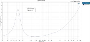
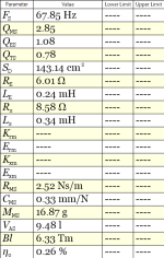
See the link to the data sheet and impedance plot and in box parameters. Note the increased Qts.
Thanks DT
https://www.falconacoustics.co.uk/downloads/Peerless/830875.pdf
I connected one of the speakers on my bench to the analyzer.
The driver is a Scanspeak HDS-P830875. I have owned it for 12 ish years and not likely anyone's favorite driver and hopefully I will not be hurting anyone's feelings while testing it.
The driver is in a ~15 liter sealed enclosure. The sealed enclosure adds a little stiffness or air suspension. I have the impression that the added air suspension is more linear than the existing mechanical suspension.
Measuring these sealed enclosures I have noted that the resonate frequency increases and that the cone excursion at the lower frequencies is reduced.
See the link to the data sheet and impedance plot and in box parameters. Note the increased Qts.
Thanks DT
https://www.falconacoustics.co.uk/downloads/Peerless/830875.pdf
Attachments
The 'in-box Qts' is actually the Qtc. What's new about this?See the link to the data sheet and impedance plot and in box parameters. Note the increased Qts.
The 'in-box Qts' is actually the Qtc. What's new about this?
There is nothing new about this.
Just for a little cognitive entertainment:
What forces are acting on the cone of the driver?
The motor of the driver is acting on the driver cone. If the motor is perfect BL is constant what ever the position of the Voice Coil in the B Field. If BL varies with the position of the Voice Coil in the B Field then things are a bit more complicated. BL is one force acting on the cone of the driver.
Stiffness of the suspension applies force to the cone
Compressed air in, terms of pounds per square inch, is another force that applies force to the cone.
Depending on sign, +/-, the suspension and and air compression can greatly effect the motion of the cone, think stored energy.
I am suspecting Amplitude Modulation not just caused by S(d)x and B(l)x.
Frequency Response and Harmonic Distortion measurements next.
Thanks DT
Hello All,
This is level and Harmonic Distortion, Scanspeak HDS-P830875 at 2.83 volts, microphone about 6 inches away from driver.
Thanks DT

This is level and Harmonic Distortion, Scanspeak HDS-P830875 at 2.83 volts, microphone about 6 inches away from driver.
Thanks DT
Is it "Peerless" perhaps?Scanspeak HDS-P830875
Hello All,
This is 2 Tone Amplitude Modulation HDS-P830875 at 4.0 volts, microphone about 6 inches away from driver.
The acquired waveform plot really shows the Amplitude Modulation.
I think that the air compression of the sealed enclosure limits the excursion of the voice coil.
Note: the side bands are even, the type of AM you would expect from Sd(x)


Thanks DT
This is 2 Tone Amplitude Modulation HDS-P830875 at 4.0 volts, microphone about 6 inches away from driver.
The acquired waveform plot really shows the Amplitude Modulation.
I think that the air compression of the sealed enclosure limits the excursion of the voice coil.
Note: the side bands are even, the type of AM you would expect from Sd(x)
Thanks DT
Last edited:
That there is some kind of modulation going on, is from a physics point of view not saying much at all.
Again, the only important question here is how significant that contribution is.
And, no, this is not evident, since that contribution is already very heavily dependent on the surface area.
I am not talking about the relationship with cone excursion in that case, but the fact that the Sd of a surround (and therefor its change) is relatively bigger for small woofers compared to bigger woofers.
So again, the fact that there is AM is not what we are looking for, that was obvious from the beginning, we need to see numbers to get a sense of its significance.
Otherwise I can claim that the position of the moon also changes BL.
No we are not talking about any driver, we are talking about physical phenomena and how significant they are.We are speaking of long throw drivers; B(l), S(d) ... are not constants.
Hello,
Amplitude Modulation caused by Force Factor Modulation shows up as f2 +/- 2f1 or odd AM side bands. The side bands in the plots above are even as in f2 +/- f1.
The AM in the above plots is clearly not caused by Force Factor Modulation.
Thanks DT
Amplitude Modulation caused by Force Factor Modulation shows up as f2 +/- 2f1 or odd AM side bands. The side bands in the plots above are even as in f2 +/- f1.
The AM in the above plots is clearly not caused by Force Factor Modulation.
Thanks DT
Are you sure it is AM modulation and not another kind of IMD ? If proper AM then the sidebands would be at the same level but they differ by about a factor of three.
Regards
Charles
Regards
Charles
Are you sure it is AM modulation and not another kind of IMD ? If proper AM then the sidebands would be at the same level but they differ by about a factor of three.
Regards
Charles
Hello Charles,
Quite sure.
We are looking at a real speaker with real measurement tools not a simulation.
If the B field and Voice Coil were completely symmetrical perhaps the side bands would be closer to the same magnitude but not in the real world.
If you like take a look at the IMD AM side bands in this Purifi data sheet.
Thanks DT
https://ptt.purifi-audio.com/document/share/28/04d9e1fb-782d-43e6-a181-7d67ed1066a7
Could it be the sideband a-symmetry stems more from spider plus surround a-symmetry than Bl(x) a-s, or is that a plain wrong assumption?
it’s evident from the time domain plot that it’s dominated by AM and not FM. Any modulation spectrum can be decomposed into its AM and FM components. Doppler distortion is a source for FM but Bl(x), Sd(x) and Bl(i) all predominantly produce AMAre you sure it is AM modulation and not another kind of IMD ? If proper AM then the sidebands would be at the same level but they differ by about a factor of three.
Regards
Charles
Well, if it is there it is certainly contained in the time domain plot. But at these small amounts it is not easily visible by eye. I even used a ruler but didn't come to any clear conclusion.
Regards
Charles
Regards
Charles
- Home
- Loudspeakers
- Multi-Way
- The importance of Kms(X) and BL(x) for mid-ranges