Blues,
I'm in the process of gathering parts for my upcoming Aleph-X attempt, where I plan on using your baords once they become available. Do your boards include spots for potentiometers / variable resistors for setting the bias and CCS AC current contribution, and if so, what type or geometry of pots have you settled on?
Thanks in advance, Terry
Terry,
It features trim pot position for adjusting diff pair bias only but not output bias. CCS current gain also. I used the in-line type of trim pot and not the triangular legged one. I'll post the space and trim pot dimensions allowed on the board when I get home.
Thanks,
allan
It features trim pot position for adjusting diff pair bias only but not output bias. CCS current gain also. I used the in-line type of trim pot and not the triangular legged one. I'll post the space and trim pot dimensions allowed on the board when I get home.
Thanks,
allan
Terry,
The space will allow for a 5mm width trim pot with 2.5mm-spaced in-line leads. Depending on how you'll be mounting the PCB...parallel to the heatsink back-plane you'd want the side adjust type: muRata PV36 or 37, Bourns 3296X or the BC CT94X will fit. For perpendicularly mounted PCBs the top adjust type will be more convenient: muRata PV36 or 37, Bourns 3296W or BC CT94W...all are multi-turns and available at Digikey.
On the AlephX as drawn by Grey Rollins R24/26 and V2 will be comprised by just one trim pot on the HRA board (a 500 ohms trimmer set to about 250 ohms before testing-fine tune for about 20mA or more later). So with R11/V1 and R33/V3 with just a trimpot (200k) for each combo.
Allan
Allan,
Thanks for providing such detailed specifics. I already was eyeing the Bourns 3296 series but had been planning based on Grey's resistor paralleled with pot scenario. Your info has saved me from having to buy the pots twice. Now I just have the big caps, inductors and trafo's left to buy for the power supply, aka the expensive stuff, although I already have the heatsinks. Picked up a boxful of Wakefield 486K's from a surplus/disposal outfit for about 5% of their new cost. Gonna use two sinks per monoblock.
Cheers, Terry
For the AX guys who have built it and for those who are planning to....
Do you find you have/will have a need for the Common-mode feedback resistors going from each output to the Source of the diff amp (or Drain of diff amp CCS)? I think some people use it to tame DC offset along with the 30 ohms of resistors to ground at each output. NP I think endorsed these but is not included in Grey's circuit. I can't find in the pile of info that is the "AX" thread reasons why it wasn't included.
Please let me know from those who have experienced it and I will try to include them in the HRA boards. Make some noise guys if you need it and if you want it.

Uli,
It's not showing on the AX wiki page circuit...I thought that's what the final circuit came to.
AR2,
Sorry, not a chance. If you're after 4A, +/-60V of the A1.2 you can up the A2 bias and rails for similar power specs.
Allan
It's not showing on the AX wiki page circuit...I thought that's what the final circuit came to.
AR2,
Sorry, not a chance. If you're after 4A, +/-60V of the A1.2 you can up the A2 bias and rails for similar power specs.
Allan
I appear to have missed this thread.
Yes, to the extent that I have power to grant permission on such things, you can X the Aleph if you can work it out on the board, but as always, Nelson is the final arbiter on such matters.
The resistors from the outputs to the input differential are useful. I suggest setting the board up to allow their use. The worst thing that can happen is that people don't put the resistors in. I have only (so far) ever posted one version of the Aleph-X. As uli noted, the resistors were suggested by Ian MacMillan later in the thread. I endorse the idea. It seems that Ian did manage to deduce what Nelson was doing in the production XA amps. Someone buy him a beer.
I'll try to keep an eye on this thread now that I know it's here, but make no promises. I'm in the midst of doing taxes, ongoing problems with my car after the kid hit me last fall, fine-tuning the line stage I'm doing for someone, planting veggies for my wife, etc. etc. etc. In other words, my usual complaint that I'm way overcommited on time. You guys have heard me gripe about this enough times, just ignore me. I'll try to drop in when I can.
If you get desperate for a guinea pig for the boards, I have most of the stuff on hand. The problem (what, you're surprised?) will be getting enough time to assemble the things and test them. Yes, I've got a moderate assemblage of test gear--no AP, sorry--it's time to play with my toys that I lack.
Grey
Thanks Grey! For your offer too. I don't have time to organize the pro boards right now not until the "smoke" clears at my end. Most probably end of April...not a promise though. Meanwhile, Ian's (Macka) guns are blazing away.
allan
allan
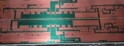

This was a kitchen table effort.
The layout was reproduced in BW onto A3 film using a large format copier.
All tracks were then ink filled by hand. It took a while.
macka.😎
The layout was reproduced in BW onto A3 film using a large format copier.
All tracks were then ink filled by hand. It took a while.
macka.😎
Ian,
That's is cool and nice! Although you seem to have run out of board space on the long edges...or is it just my eyes? That proves again the kitchen table's versatility...🙂 Ian, I salute your efforts and patience.
Allan
That's is cool and nice! Although you seem to have run out of board space on the long edges...or is it just my eyes? That proves again the kitchen table's versatility...🙂 Ian, I salute your efforts and patience.
Allan
The board was obnly just big enough, I thought I had more space.
Ah, well not bad for a first effort.
Ian
Ah, well not bad for a first effort.
Ian
No Ian, that's really baaad...wickedly sick!....if you know what I mean. Filling-in every trace must have been the greatest effort in the project. I have found how to fill-it up with cross-hatch after converting the drawing to 2D in AutoCAD so if you need another run I'll send you a printout.
BTW your board does not include the traces and positions for the R's from output to S of diff pair for the Aleph X config as Grey described in his post above.
allan
BTW your board does not include the traces and positions for the R's from output to S of diff pair for the Aleph X config as Grey described in his post above.
allan
Yeah,
I did it while watching season 1 of Tv series 24 Hours on DVD. I don't know how I did it b/n agent Bower and the bad guys.
Okay Allan,
If you could sent the filled layout for the HR2 pcb it would save the eyes....LOL.
cheers
Ian
I did it while watching season 1 of Tv series 24 Hours on DVD. I don't know how I did it b/n agent Bower and the bad guys.
Okay Allan,
If you could sent the filled layout for the HR2 pcb it would save the eyes....LOL.
cheers
Ian
- Status
- Not open for further replies.
- Home
- Amplifiers
- Pass Labs
- The HotRod Aleph Circuit Board