After reading this thread over and over again, here's my take on this -
I am trying to narrow it down by eliminating the obvious.
I think its not related to ESR, nor inductance (of filter capacitors) otherwise you could use ten 1000uf caps in parallel and that would be end of story. In fact as per one post (by carlos himself?) more capacitors in parallel didn't improve anything and actually made it worse.
I dont think its the diode ringing either because diode ringing would not worsen/improve with increase/decrease of filter capacitance or number of caps and can be taken care of by Schottky, HEXFRED etc.. diodes and the MUR860 are already fast/soft diodes so ringing shouldn't be that bad.
That leaves me to believe that its got to do something with decoupling or the impedance of the PS. Anybody have any thoughts on this ?
By murat:
Do you think the idea might be relevant to solid state amps? Read first paragraph after "Power Supply Decoupling and Grounding" in Leach's power supply:
Along the same line, consider the "s" word,
http://www.hagtech.com/pdf/snubber.pdf
Entitled "Calculating the Optimum Snubber"
Of particular interest is Jim Hagerman's asertion that values need to be based upon measured values for other components in the power supply. This means optimum values will change for different transformers.
percy said:That leaves me to believe that its got to do something with decoupling or the impedance of the PS. Anybody have any thoughts on this ?
See this post and the one following:
http://www.diyaudio.com/forums/showthread.php?postid=532832#post532832
Check this out....
Thanks for pointing that out. Found some interesting read after a google search..
www.calex.com/pdf/3power_impedance.pdf
See page 4 especially. and 5/6 also.
Thanks for pointing that out. Found some interesting read after a google search..
www.calex.com/pdf/3power_impedance.pdf
See page 4 especially. and 5/6 also.
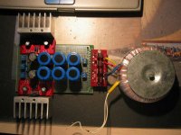
finally got round to doing it myself. It should look something like in the pic attached.
psu consists mainly of parts-bin stuff; 3x4700 40V BC components caps, 1x 1000uF Panasonic FC and a few 100 - 220 nF bipolar film caps (no brand?)
To complete this project i had to dismantle an older brianGT pcb-based clone.
Now all i have to do is find another enclosure, which is always the hardest part of building clones... 😉
Attachments
percy said:
<snip>
That leaves me to believe that its got to do something with decoupling or the impedance of the PS. Anybody have any thoughts on this ?
Ofcourse it is. This is not rocket science. A properly decoupled, low/linear impedance, low noise supply is what any amplifier needs to work at its best. 😉
matjans said:Now all i have to do is find another enclosure, which is always the hardest part of building clones... 😉
matjans, forget the enclosure for now, listen to the amp.
It will work without the enclosure.😀
Let it play for some days.
Carlos,
This sounds very promising.
For C3 and C4, the two 10,000uF caps, did you bet better results using 10,000uF caps or a series of smaller ones paralleled?
Thanks,
KT
This sounds very promising.
For C3 and C4, the two 10,000uF caps, did you bet better results using 10,000uF caps or a series of smaller ones paralleled?
Thanks,
KT
KT said:Carlos,
This sounds very promising.
For C3 and C4, the two 10,000uF caps, did you bet better results using 10,000uF caps or a series of smaller ones paralleled?
Thanks,
KT
I have very good results with both ways.
The single 10,000uf caps in the schematic is an example, a starting point.
2x4,700uf will have similar results, the snubber with THOSE values is the most important thing here.
Around 10,000uf per rail is also a starting point.😉
matjans said:finally got round to doing it myself. It should look something like in the pic attached.
psu consists mainly of parts-bin stuff; 3x4700 40V BC components caps, 1x 1000uF Panasonic FC and a few 100 - 220 nF bipolar film caps (no brand?)
To complete this project i had to dismantle an older brianGT pcb-based clone.
I need to implement this strategy with a very recent Brian GC kit (3875) I built. I got crappy results driving my bass bins with the kit as supplied. My setup looks exactly like what you have in your pic. Do you have a marked up schemo of what you did to Brian's kit? Or maybe I could just email and get some help. I can build the PS from Carlos's schemo but I'm a little sketchy of how to sync up Brian's wiring configuration from the PS board to the chip board.
What chip are you using?
Regards,
Jim D.
if you mean subwoofers, the lm3875 probably can't deliver enough power. try using 3886's or something else like opa549's.
i've only replaced the 'original' 1000uF caps with 100uF's bypassed with 220nF bipolars on brian's board.
i've only replaced the 'original' 1000uF caps with 100uF's bypassed with 220nF bipolars on brian's board.
matjans said:if you mean subwoofers, the lm3875 probably can't deliver enough power. try using 3886's or something else like opa549's.
i've only replaced the 'original' 1000uF caps with 100uF's bypassed with 220nF bipolars on brian's board.
The woofers are high efficiency altecs doing more mid bass duty. They don't need alot of power.
I'll get some parts and give it a go.
Jim D.
Well I tried the psu today, using a 3.8k resistor, 2 2200uf caps, and one 6800uf cap per rail in place of the 2.2k resistor and 10,000 uf cap. All I can say is DAMN. 😱 😀 It sounds excellent! The bass not only seems deeper, but it is much more controlled, as well. The highs and mids aren't damped down at all, like they were without the snubber and just the caps (I tried without the snubber first).
For my amplifier I have an lm3875 with 2200uf caps. I haven't tried replacing them with 100uf, though, because I'm quite satisfied with the sound as it is. I'm gonna let the psu burn in for a while, and hopefully it'll sound even better. 😎
For my amplifier I have an lm3875 with 2200uf caps. I haven't tried replacing them with 100uf, though, because I'm quite satisfied with the sound as it is. I'm gonna let the psu burn in for a while, and hopefully it'll sound even better. 😎
matjans said:did you use a zobel on the amp's output?
No I did not. I actually used the schematic from Brian's amp, but used a 31k feedback resistor. Actually, I've never used a zobel on any amp. Would you recommend using one?
Man, I can't stop listening now. 😀 Everything is so clear and defined! 😎
[offtopic]
that's a pretty high gain for a clone.
see this thread for a discussion on zobels with clones. It does make a difference (in a good way), will cost you next to nothing and is exceedingly simple to make.
i stuck with carlos' suggestion (which is also in the lm3875 appnotes, i believe) to use a 2,7R + 0,1uF polyprop (i think i used wima mkp) [/offtopic]
So I left for a little while this evening while the amp was playing, and when I returned I found that the chips were putting out about 30vdc into the speakers! 😱 Apparently I had a bad solder connection at the negative rail and the wire came detatched while I was gone, so there was only positive and ground. Luckily the speakers were fine.
Anyway, yeah, I know the gain is pretty high, but I don't exactly have a high output CD player. I can listen fairly comfortably at full volume with a 20k, so I just went ahead and used a 31k.
I'll give that zobel a shot as soon as I get some more .1uf capacitors and a couple resistors. That thread was very helpful, thank you. 🙂
I tried the zobel tonight, using a 10 ohm resistors and .068uf capacitors. Though it did not increase the bass or give the amp better bass control, it made the vocals seem so alive! 😀 Overall I am very happy. It's only getting better as it burns in, too.  😎
😎
😎I tried the zobel tonight, using a 10 ohm resistors and .068uf capacitors
Hi Carlos
Pardon my ignorance but what you call 'zobel' is in fact just a decoupling cap with a series resistor to reduce the Q, right?
So, it may sound a bit better than straight bypassing of the cap. It's strange that no one is comparing the cap+resitor to just cap - it would seem the most obvious experiment.
Audio Research have been doing something similar for years, they even hold a patent for it. The main filter caps in PH3 per example are in series with a parallel combination of 2.7uH and 55R and the 'zobel' close to the amp stages is 1R in series with 2uF.
This approach seems to also deliver a more constant PS impedance over the audio band.
analog_sa said:Hi Carlos
Pardon my ignorance but what you call 'zobel' is in fact just a decoupling cap with a series resistor to reduce the Q, right?
So, it may sound a bit better than straight bypassing of the cap. It's strange that no one is comparing the cap+resitor to just cap - it would seem the most obvious experiment.
I did.
As you can see on my schematic I use a 0.1uf film cap bypassing the big one.
But that's not enough to make the amp sound decent with high capacitance.
In practice, it doesn't solve much.
What really makes the difference is the snubber, with 1R + 100nf.
- Status
- Not open for further replies.
- Home
- Amplifiers
- Chip Amps
- The (high-cap.) unregulated PSU for chipamps